Flexible optical illumination system

a flexible, optical illumination technology, applied in the direction of optical elements, planar/plate-like light guides, instruments, etc., can solve the problems of limiting the degree to which the size of the end product (e.g., mobile phone) can be reduced, rigid light guides tend to have substantial size impacts on the electronic devices in which they are used, and restrict manufacturers from implementing various configurations. , to achieve the effect of reducing manufacturing and assembly time and costs

Inactive Publication Date: 2007-10-18
NOKIA CORP
View PDF16 Cites 14 Cited by
  • Summary
  • Abstract
  • Description
  • Claims
  • Application Information

AI Technical Summary

Benefits of technology

[0006] In yet another aspect, the manufacturing of a flexible lightguide may be integrated with the overall assembly process and thus reduce manufacturing and assembly time and costs. For example, the lightguide may be applied as a liquid adhesive that both forms the flexible lightguide as well as bonds the multiple components of the electronic assembly together. The lightguide may be implemented for either data transfer processes or for decorative purposes.

Problems solved by technology

Furthermore, rigid lightguides tend to have substantial size impacts on the electronic devices in which they are used.
For example, the size of a rigid lightguide often limits the degree to which the size of the end product (e.g., mobile phone) can be reduced.
The inflexibility of rigid lightguides also restricts manufacturers from implementing various configurations when designing electronic devices.
Additionally, multiple light emitting sources must often be used due to the inability of a single light emitting source to provide illumination to all the desired components and to multiple surfaces of a device.
The need for additional light emitting sources further increases the power consumption of electronic devices.
In mobile devices where battery power is at a premium, the addition of a lighting device may significantly decrease the battery life.

Method used


Image

  • Flexible optical illumination system
  • Flexible optical illumination system
  • Flexible optical illumination system

Examples


Embodiment Construction

[0020] In the following description of various embodiments, reference is made to the accompanying drawings, which form a part hereof, and in which is shown by way of illustration various embodiments in which the invention may be practiced. It is to be understood that other embodiments may be utilized and structural and functional modifications may be made without departing from the scope of the present invention. Although various embodiments are described by reference to a mobile communication device (e.g., a mobile phone), this is only one example of a device in which various aspects of the invention may be implemented. Other examples include, but are not limited to, PDAs, remote controls, laptop computers and watches.

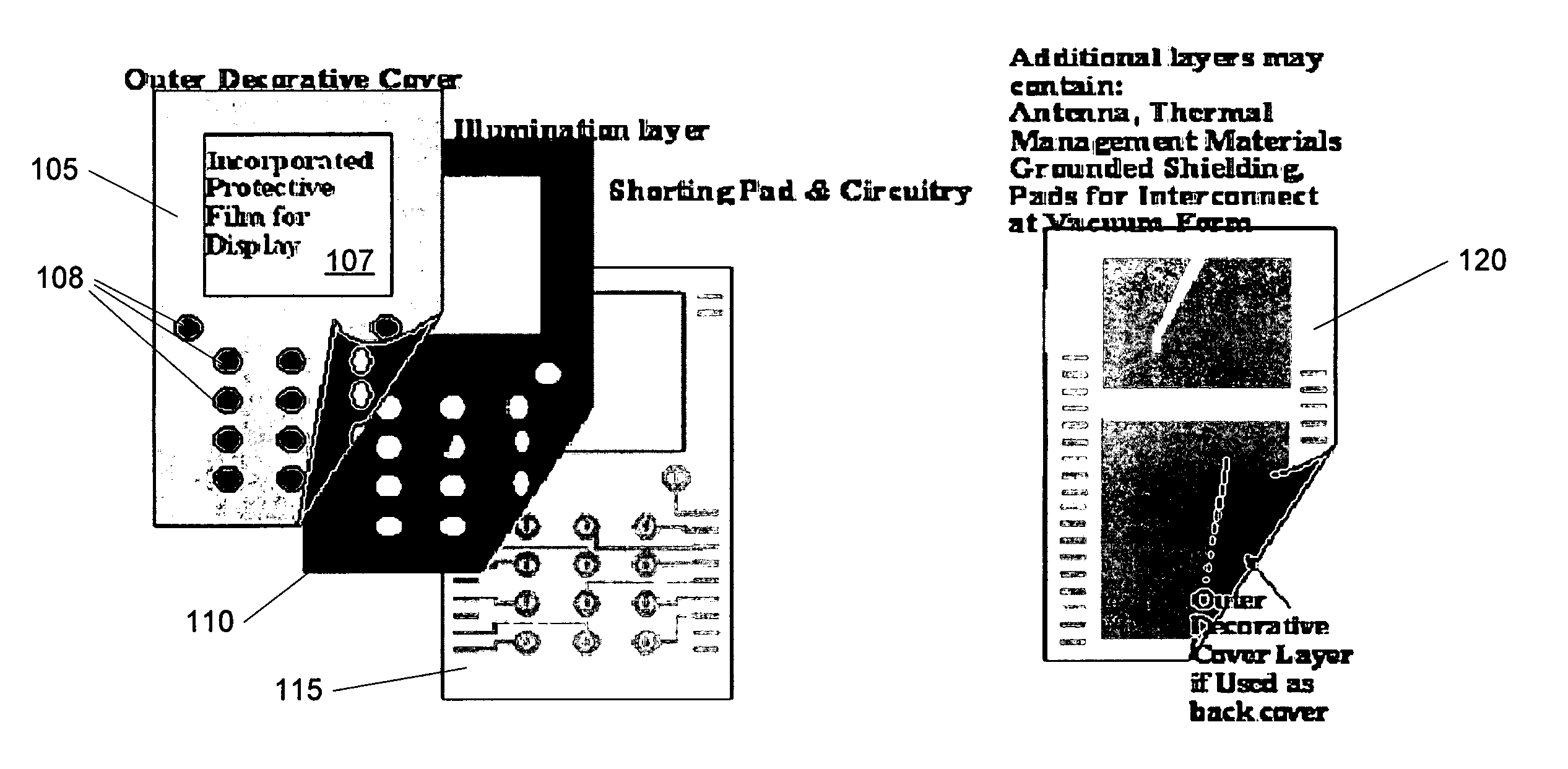
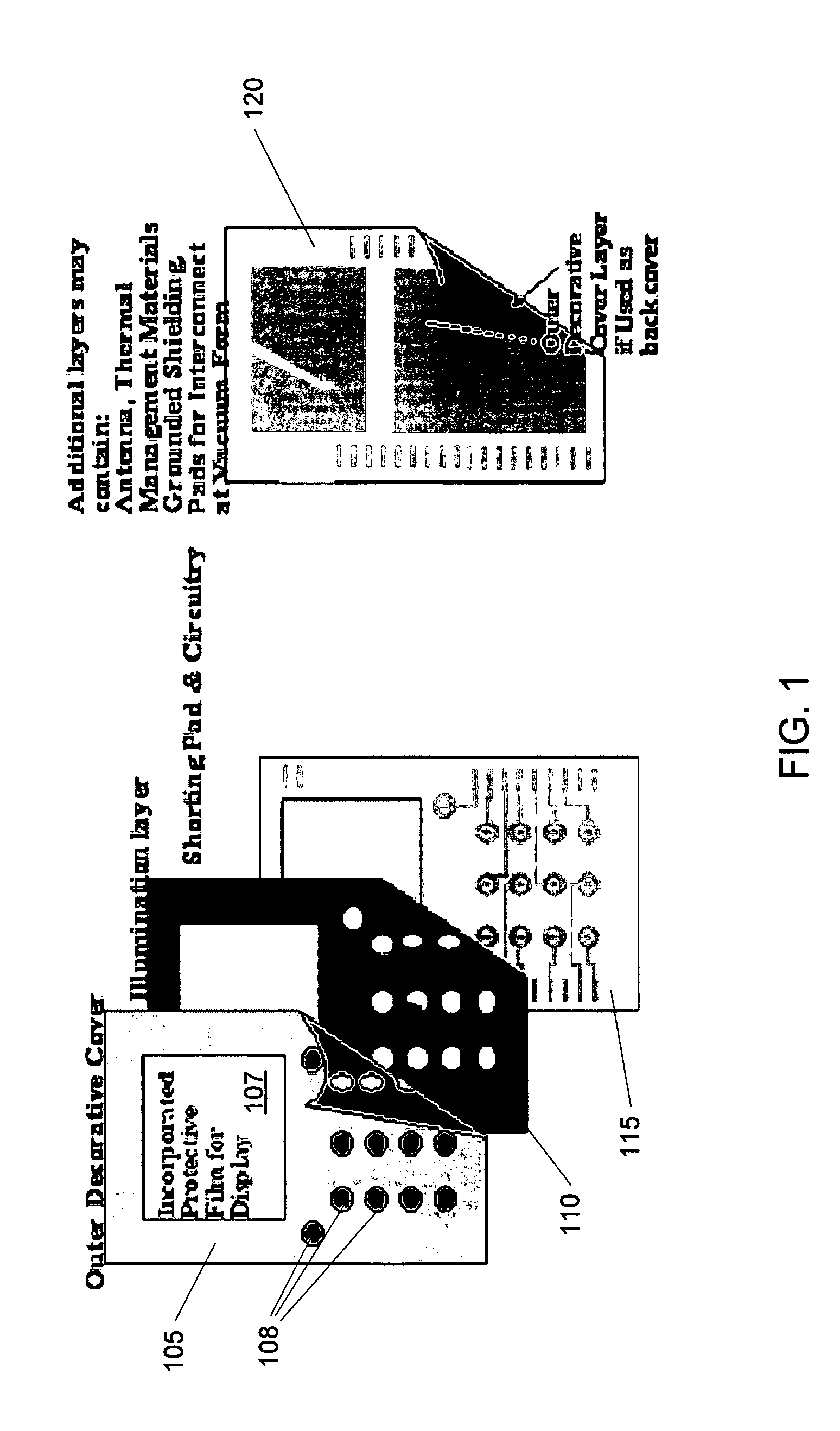
[0021]FIG. 1 illustrates multiple layers of a mobile communication device according to an illustrative embodiment. The multiple layers include a front outer cover 105, an illumination layer 110, a circuitry layer 115 and a back outer cover 120. Each layer serves vari...


PUM


Abstract

A flexible optical illumination system may be used to illuminate components or areas of an electronic device such as mobile and portable communication devices. The flexible lightguide may manipulate and channel light selectively throughout an electronic assembly providing illumination for selective areas or an entire device. The lightguide may further include various filters and components for modifying, detecting and processing light and characteristics thereof. A flexible lightguide may be created from numerous optically transparent materials and processes such as film lamination, adhesive binding and molding. The lightguide may be created by a process that combines the manufacturing and assembly of the lightguide with the manufacturing and assembly of other components of the device. The lightguide may further be integrated into various mechanical or electronic components. The illumination system may also be used in different applications including decoration, illumination, alarms, message transfer and data transfer.

Description

FIELD OF THE INVENTION [0001] The invention relates generally to a method and a system for providing illumination to components of an electronic. Specifically, the invention relates to the formation of a flexible optical lightguide for providing 2D and 3D illumination to components of an electronic assembly and / or the entire assembly. BACKGROUND OF THE INVENTION [0002] For both aesthetic and functional reasons, illumination has become an expected feature of electronic devices such as mobile phones, remote controls, miniaturized PC and personal data assistants (PDA). Many electronic devices use illuminated components to indicate a status of the device while other components such as an antenna on a mobile telephone might be illuminated for decorative purposes. In one example, mobile telephone users often attempt to make calls in poorly lit areas and must make several attempts. As such, illuminated keypads have become popular for resolving such issues. Another component of electronic d...

Claims


Application Information

Patent Timeline
Patent Type & Authority Applications(United States)
IPC IPC(8): H04B1/06
CPCG02B6/0018G02F2201/58G02B6/0021
Inventor CUNNINGHAM, ROBERTDUNFORD, STEVEN O.NOUSIAINEN, JAAKKOVATANPARAST, RAMIN
Owner NOKIA CORP
Why Eureka
Try Eureka