
Method for safely removing connecting device of peripheral equipment of computer

a technology of peripheral equipment and connecting device, which is applied in the direction of coupling device connection, metal working apparatus, manufacturing tools, etc., can solve the problems of complicated structure and inability to use electronic devices, and achieve the effect of safely and easily removing the first devi

Inactive Publication Date: 2007-10-18
CHIEN MIN RU
View PDF10 Cites 0 Cited by
  • Summary
  • Abstract
  • Description
  • Claims
  • Application Information

AI Technical Summary

Benefits of technology

[0007] The primary objective of the present invention is to provide a method for easily and safely removing a first device from a second device.
[0008] Another objective of the present invention is to provide a method that is used for removing a first device from a second device in a easier and safer manner, without damaging the first device or the second device during the pulling process.
[0009] A further objective of the present invention is to provide a safely pulling method, wherein the loop of the strap mounted on the first device allows passage of a user's one finger, so that the user's one finger directly exerts a straight outward force on the loop of the strap to easily remove the first device from the second device in a straight manner without producing deflection, thereby removing the first device from the second device easily and safely without damaging the first device or the second device during the pulling process.
[0010] A further objective of the present invention is to provide a safely pulling method, wherein the strap is foldable easily without occupying space.
[0011] In accordance with one embodiment of the present invention, a method is provided to safely remove a first device from a second device. Firstly, a strap is provided. Secondly, a first portion of the strap is connected to the first device. Finally, a second portion of the strap is made into a loop. A user can insert a finger through the loop and pull the strap to disengage the first device from the second device.

Problems solved by technology

This arrange however cannot be used in electronic devices since their weights are too light to disengage them from other devices.
Furthermore, the structure is complicated for providing the pulley 66 in the housing 61 and making the slot 82 in the housing 61.

Method used


Image

  • Method for safely removing connecting device of peripheral equipment of computer
  • Method for safely removing connecting device of peripheral equipment of computer
  • Method for safely removing connecting device of peripheral equipment of computer

Examples


Embodiment Construction

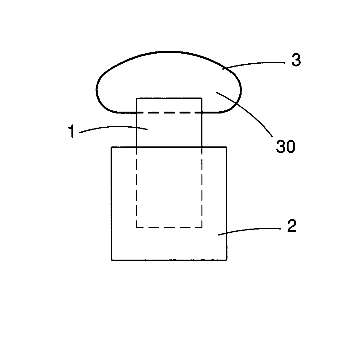
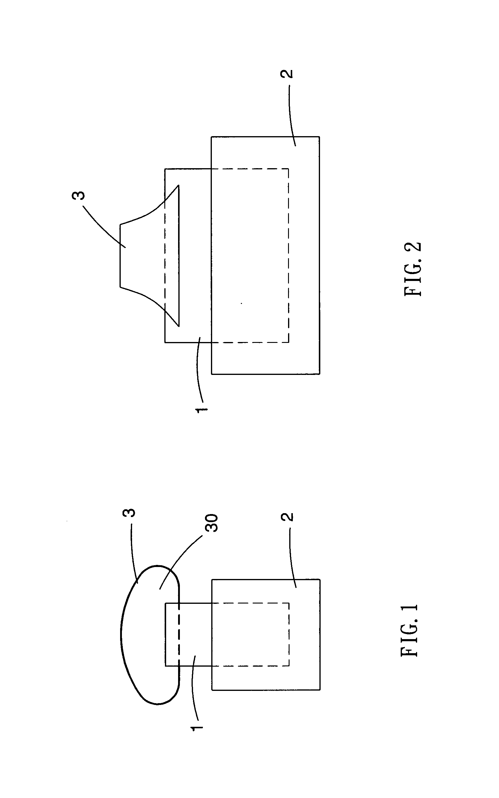
[0025] Referring to the drawings and initially to FIGS. 1 and 2, a method is used to safely remove a first device 1 from a second device 2 in accordance with the preferred embodiment of the present invention. Firstly, a strap 3 is provided. Secondly, a first portion of the strap 3 is connected to the first device 1. Finally, a second portion of the strap 3 is made into a loop 30.

[0026] Preferably, the strap 3 is made of plastic material, such as PVC or the like.

[0027] As shown in FIGS. 1 and 2, the strap 3 is attached to the first device 1 and is formed with a loop 30 protruding from the first device 1.

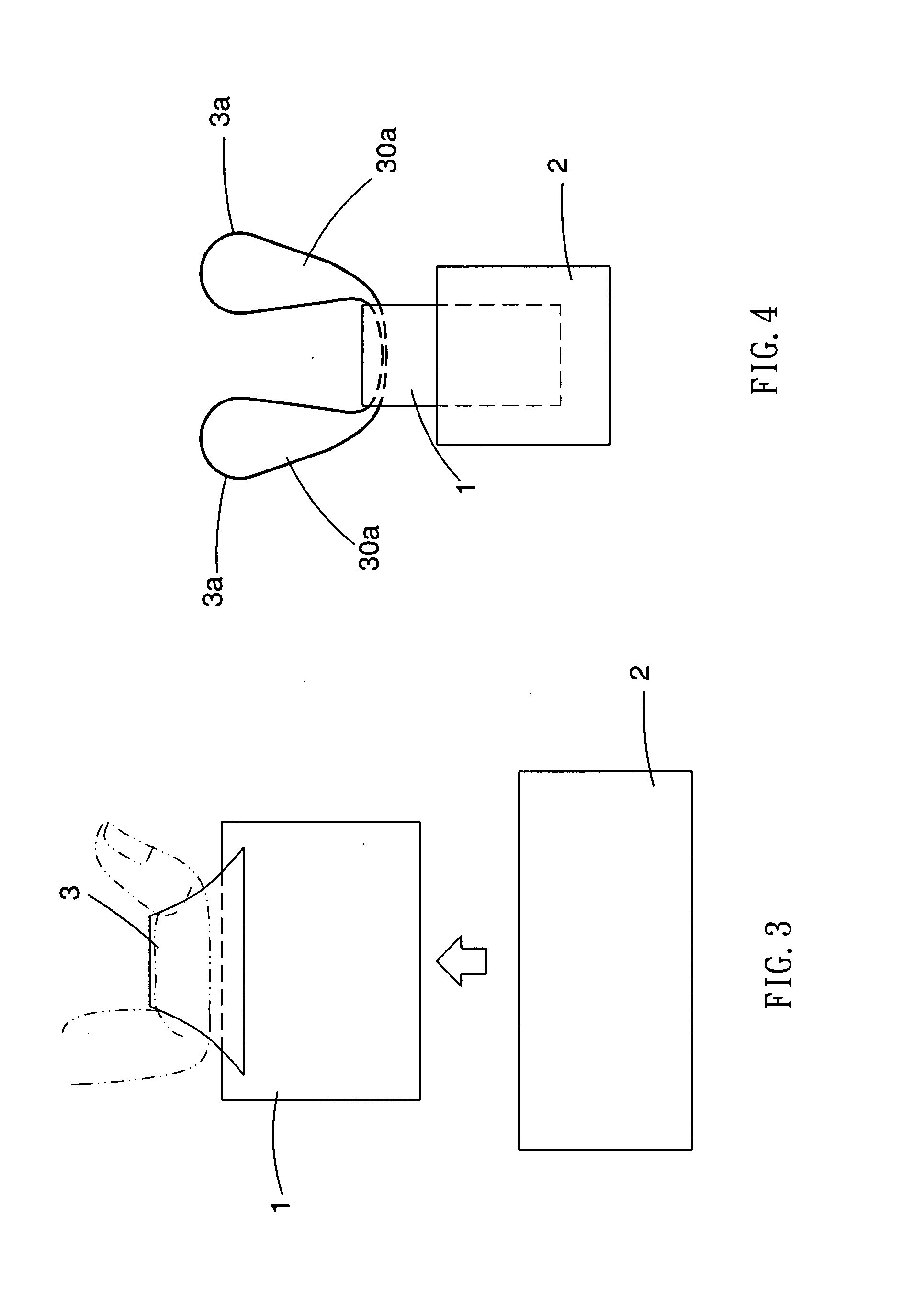
[0028] As shown in FIG. 3, the loop 30 of the strap 3 is used to receive a user's one finger so that the user's one finger directly exerts an upward force on the loop 30 of the strap 3 to easily remove the first device 1 from the second device 2 in a straight manner without producing deflection, thereby removing the first device 1 from the second device 2 safely without damaging th...


PUM

PropertyMeasurementUnit
Weightaaaaaaaaaa
Forceaaaaaaaaaa

Abstract

A method is used for safely removing a first device from a second device, e.g., removing a first connector from a matching second connector or removing an interface converter from a mother board of a computer. Thus, the loop of the strap mounted on the first device allows passage of a user's one finger so that the user's one finger directly exerts a straight outward force on the loop of the strap to easily remove the first device from the second device in a straight manner without producing deflection, thereby removing the first device from the second device easily and safely without damaging the first device or the second device during the pulling process.

Description

CROSS-REFERENCE [0001] The present patent application is a divisional application of U.S. patent application Ser. No. 11 / 012,136 which is incorporated herein for reference.BACKGROUND OF INVENTION [0002] 1. Field of Invention [0003] The present invention relates to a method for safely removing a connecting device of a peripheral equipment of a computer, and more particularly to a method for easily and safely removing a first device from a second device, e.g., removing a first connector from a matching second connector or removing an interface converter from a mother board of a computer. [0004] 2. Related Prior Art [0005] Referring to FIG. 10, a conventional connector 8 includes a first side attached to a serial bus 80 and a second side detachably inserted into a slot 90 of a mother board 9 of a computer. However, the connector 8 only includes a smaller portion protruding from the slot 90 of the mother board 9, so that a user has to exert a larger pulling force to pull the connector 8...

Claims


Application Information

Patent Timeline
IPC IPC(8): H01R13/00
CPCH01R13/6335Y10T29/53283H01R12/79
Inventor CHIEN, MIN-RU
Owner CHIEN MIN RU
Learn More