
Fan blade assembly for electric fan

Inactive Publication Date: 2007-10-18
SUNBEAN PROD INC
View PDF6 Cites 15 Cited by
  • Summary
  • Abstract
  • Description
  • Claims
  • Application Information

AI Technical Summary

Benefits of technology

[0009] The invention relates to fans and fan blade assemblies designed f

Problems solved by technology

If the solidity is too low, the airflow from the fan may separate.
While the pressure capability of a fan increases with increasing solidity, skin friction losses will also increase.
A larger difference in velocity on each side of the blade is associated with a larger difference in static pressure on each side, leading to additional load.
As discussed above, efficiency may, however, be reduced with increasing solidity.

Method used


Image

  • Fan blade assembly for electric fan
  • Fan blade assembly for electric fan
  • Fan blade assembly for electric fan

Examples


first embodiment

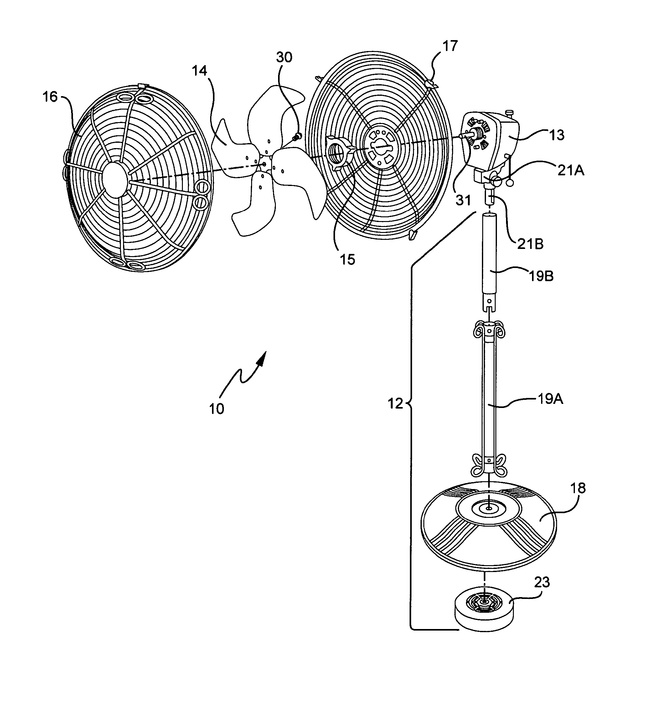
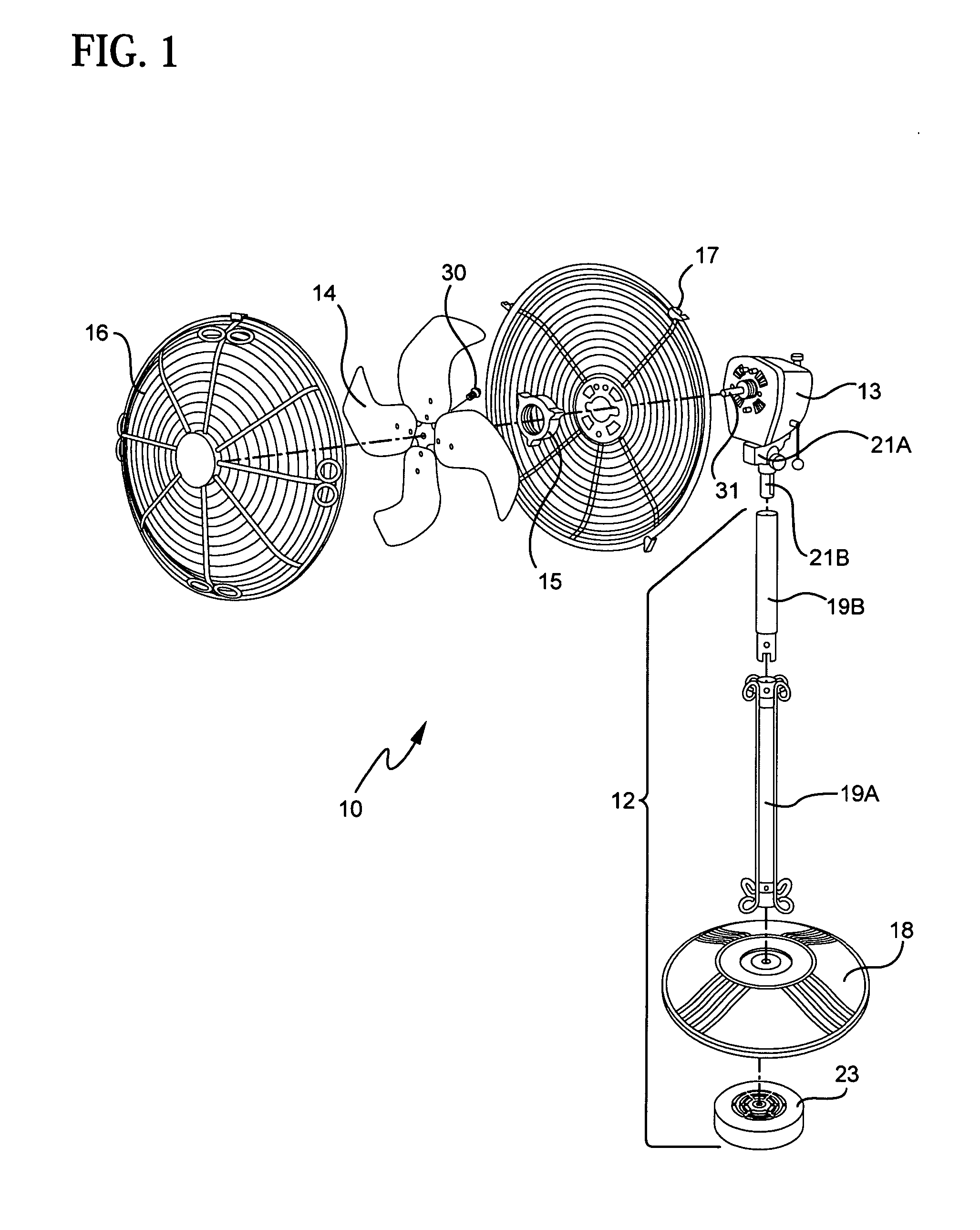
[0030] A portable electric fan 10 according to the invention is shown in FIG. 1. The fan includes a support 12, an electric motor assembly 13 mounted to the support, a fan blade assembly 14 operatively associated with the electric motor assembly 13, and a grill 16 enclosing the fan blade assembly. The grill includes two halves that are connected by wing clips 17. A grill nut 15 connects the rear half of the grill to the housing for the motor assembly 13. This type of fan 10 is known as a stand fan. The support includes a base 18, a long extension pole 19A coupled to the base, and a short extension pole 19B. The short extension pole 19B has a lower end of reduced diameter that extends within the top end of the long pole 19A. A set screw is employed to lock the poles together. The motor 13 is coupled to the top end of the short pole 19B by a bracket 21 A including a neck 21B. The neck 21B extends into the top end of the short pole 19B and is affixed thereto by a set screw. A weight 23...

second embodiment

[0039] A fan blade assembly 114 according to the invention is shown in FIGS. 9 and 10. The assembly includes five identical blades 120 that are secured to a central hub 122. The hub 122 includes a generally hemispherical body. The rear side of the hub includes five pairs of threaded openings (not shown) used for securing the blades 120. It further includes a center opening 124, as shown in FIG. 11, for receiving the shaft of a motor (not shown).

[0040] Each blade 120 is preferably made from aluminum and has a substantially uniform thickness. In this embodiment, the thickness of the airfoil portion of the blade is about 1.5 mm. As discussed above with respect to the first embodiment, the blade thickness can vary over a range without materially affecting performance. The blade includes an inner or root portion 134 that may or may not have the same thickness as the airfoil portion of the blade. The inner portion includes a curved inner edge 136 and a generally arcuate boundary 138 that ...


PUM


Abstract

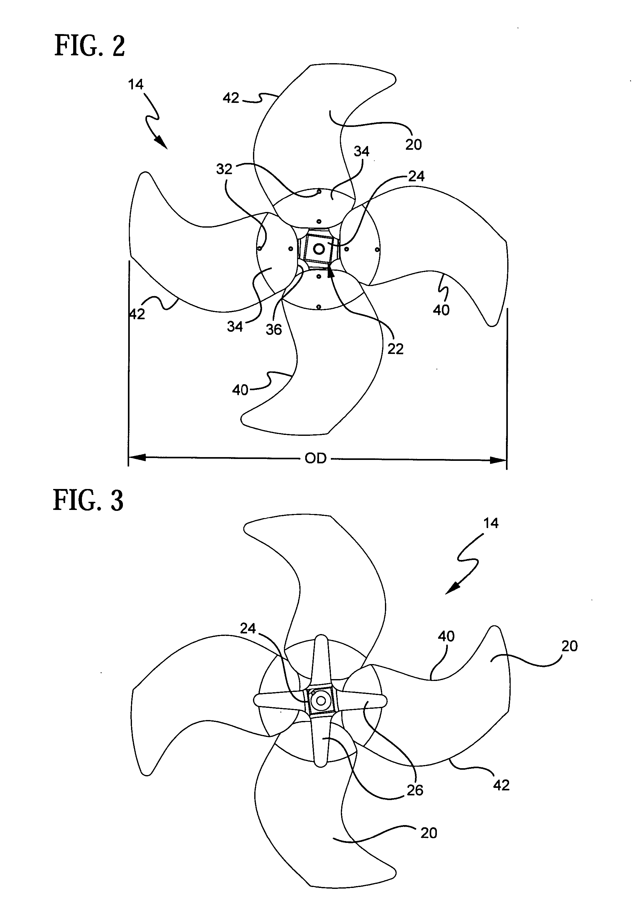
Fan blade assemblies are provided for quiet and efficient operation in portable electric axial flow fans intended for home or office use. The blades of the fan blade assemblies include a forward sweep to provide relatively quiet operation. The camber lines of the blades are curved to provide generally concave pressure surfaces and generally convex suction surfaces.

Description

BACKGROUND OF THE INVENTION [0001] 1. Field of the Invention [0002] The field of the invention relates to electric fans and blade assemblies for such fans. [0003] 2. Brief Description of the Related Art [0004] Electric fans have a variety of uses and are designed in various ways to provide desired air flows. Axial flow fans move air substantially parallel to the axis of rotation of the fan blade assembly. The operating characteristics of axial flow fans can vary significantly depending on parameters such as blade width and shape and the number of blades in the assembly. [0005] A number of terms are employed to described the physical characteristics of axial flow fans. The leading edge is the edge of the blade that first meets the air as the blade is rotated. Blades also have trailing edges. The camber line is a line extending through the center or midpoint of a blade between the leading edge and the trailing edge. An axial flow fan commonly has a curved camber line. The camber angle...

Claims


Application Information

Patent Timeline
IPC IPC(8): F04D25/08
CPCF04D29/384
Inventor NAKANO, TSUGUJIHINCH, DANIELYOSHINAKA, TSUKASA
Owner SUNBEAN PROD INC
Learn More