
Latch and latch striker interface improvements

a technology of latch striker and latch, which is applied in the field of closures, closure systems, and closures, clasping and latching devices, can solve the problems that the prior art does not address the improvement of the interface between the latch striker and the latch, and achieve the effect of reducing or eliminating noise generation

Inactive Publication Date: 2007-10-18
A RAYMOND & CO
View PDF28 Cites 27 Cited by
  • Summary
  • Abstract
  • Description
  • Claims
  • Application Information

AI Technical Summary

Benefits of technology

The patent is about an improved latch and latch striker interface that reduces noise and movement. The bridge of the striker is designed to contact a flexible wall or area of the latch, creating a better fit and reducing noise. The bridge can also have a spherical or arc shape to prevent vibration and movement. The engagement post can have a formed or pre-assembled ball for latches requiring rotational movement. The non-symmetrical features of the latch striker bridge provide load bearing surfaces for a drawer slide type action and will provide detent restraint. The assembly of the latch striker bridge to base configurations is controlled through limit stops and deformation or welding of the bridge ends. The application of an arc or spherical feature on the striker bridge or engagement post provides a nested effect that requires a lifting or climbing effect between the mating surfaces in order to move linearly apart, reducing noise and movement due to vibration.

Problems solved by technology

The interface between the latch striker and the fishmouth of the latch body is the source of many undesirable mechanical properties, particularly in automotive applications, such as too much or too little friction, noise generation, “chucking” which generally refers to relative motion between the latch striker and latch body or clasp when in the latched condition, and motion in other dimensions and degrees resulting from operational vibration.
Although improvements and alterations have been made to both latch and latch striker designs, the prior art does not address improvement of the interface between the latch striker and the latch, and specifically with the fishmouth of the latch body.

Method used


Image

  • Latch and latch striker interface improvements
  • Latch and latch striker interface improvements
  • Latch and latch striker interface improvements

Examples


Embodiment Construction

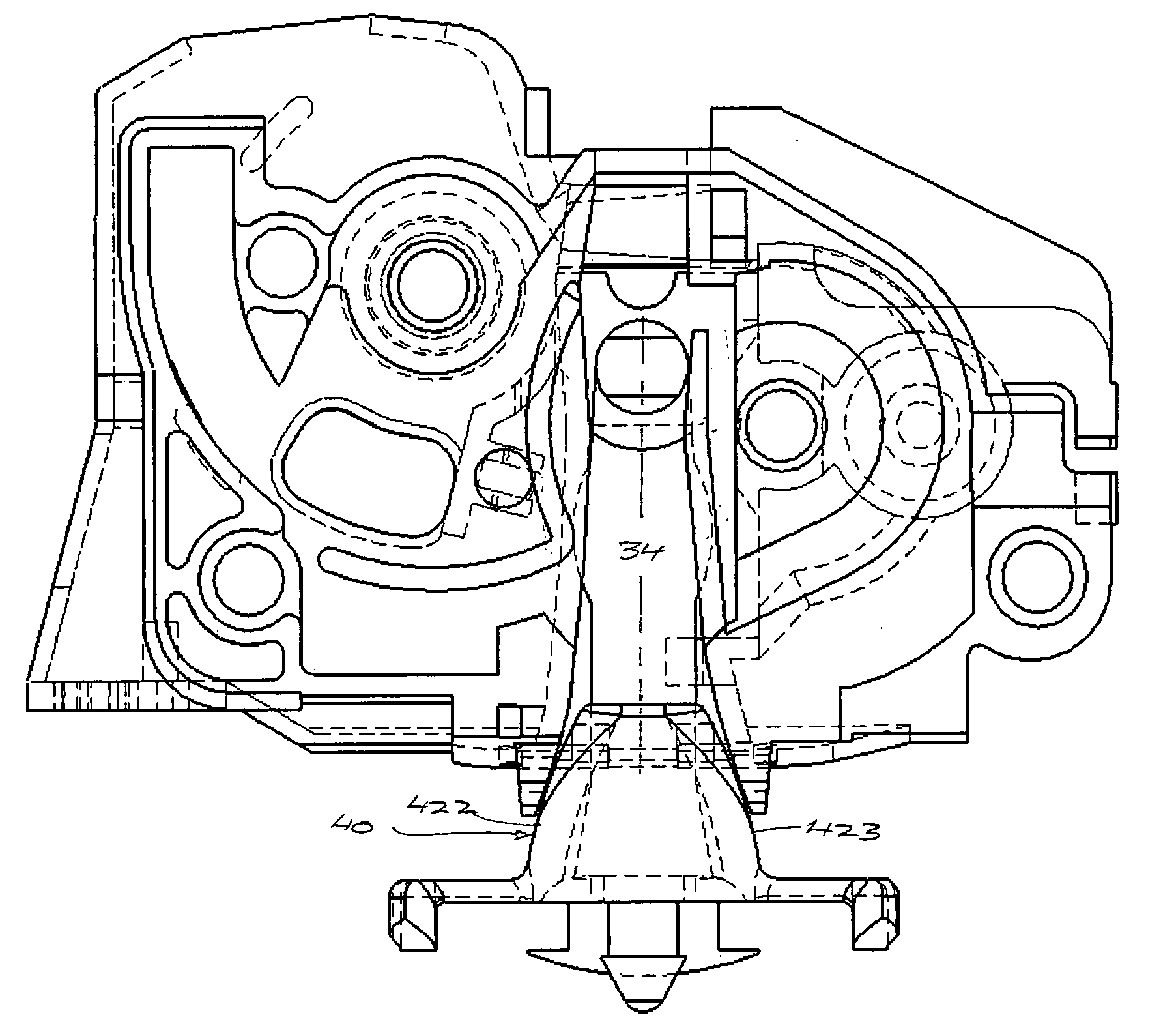
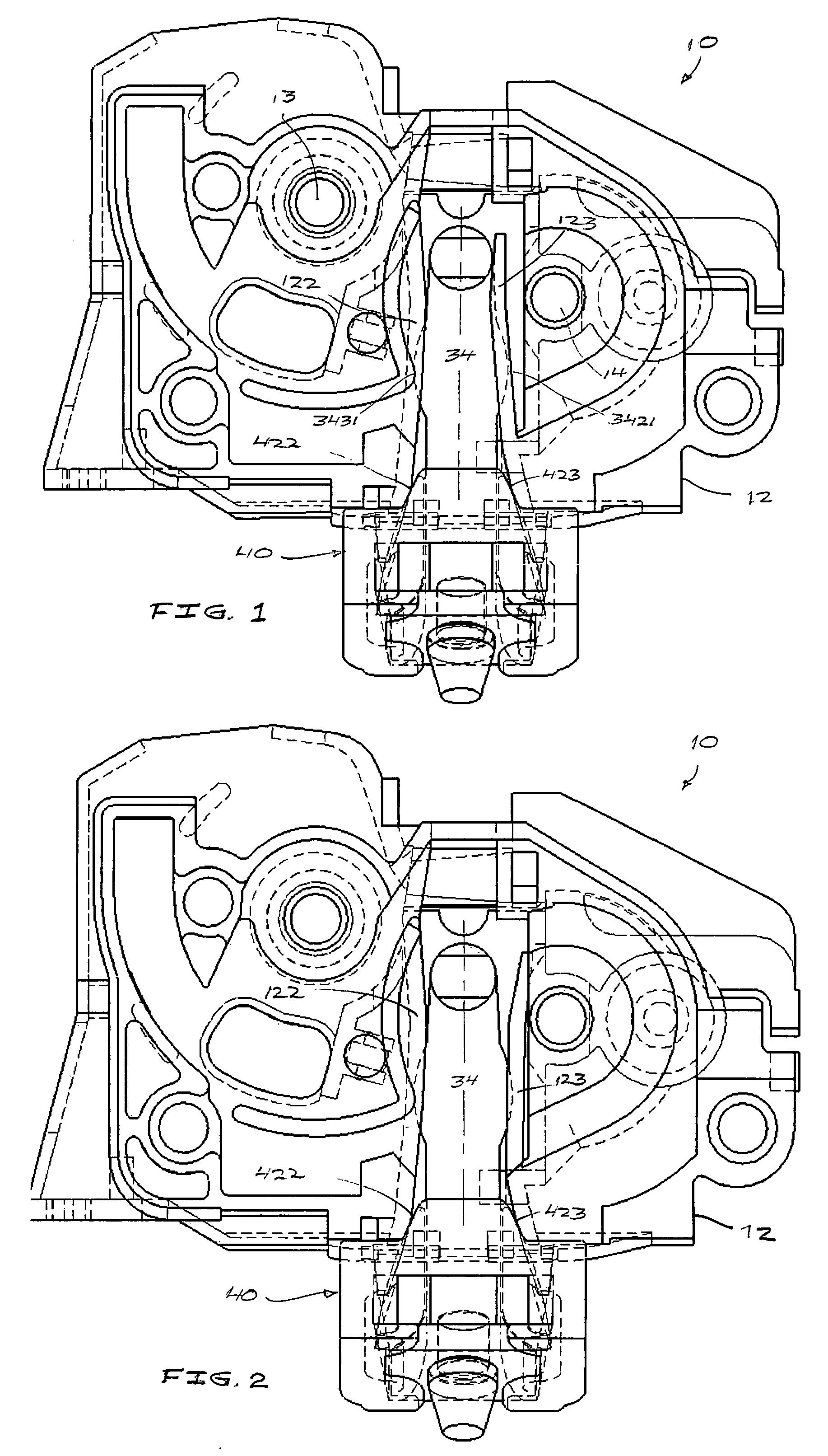
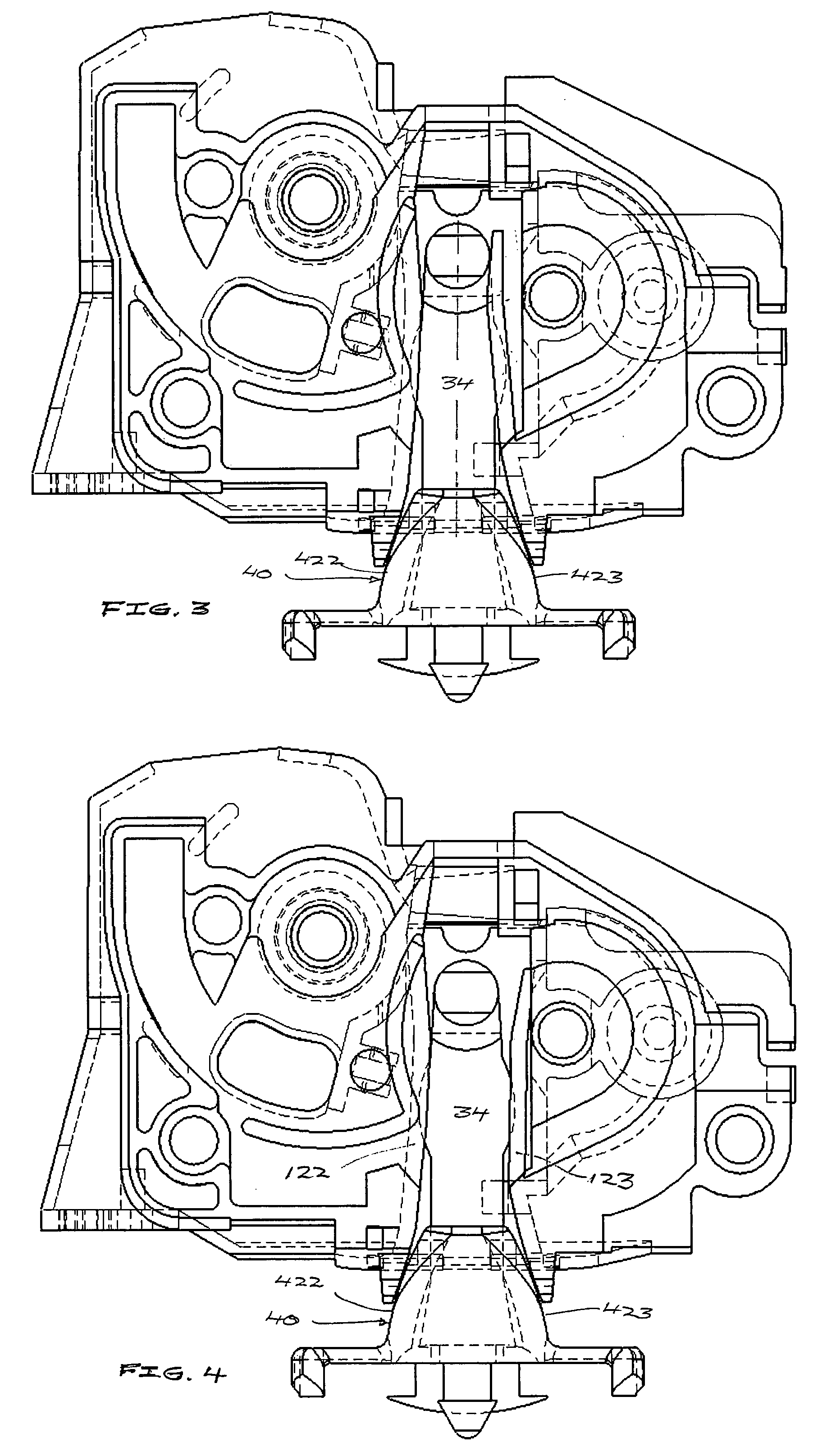
[0025]Referring to FIGS. 1 and 2, there is shown a latch, generally indicated at 10, which includes a latch body, generally indicated at 12. The latch body houses latch components such as a catch and pawl (not shown) which are rotationally mounted within the latch body, for example at pins 13 and 14. The disclosure includes any type of latch which operates in cooperation with a latch striker as further described, including but not limited to any of the different types of latches used in automotive applications as for example for passenger compartment door latching and seating and other closure applications. Some representative latches which can be used in accordance with some aspects of the disclosure include automotive latches as produced by produced by the G-Com, Magna and Kiekert corporations.

[0026]With continuing reference to FIGS. 1 and 2, and further reference to FIGS. 3, 4, 5 and 6, the latch body 12 includes a fishmouth 20 which is formed or defined by an opening 21 in an ex...


PUM


Abstract

A latch and latch striker interface including a latch striker which has a contoured bridge configured for insertion into and engagement with the fishmouth of a latch body, at least one wall in the fishmouth being at least partially flexible and flexed or deformed by contact with a contoured or protruding profile of the latch striker bridge for an anti-vibration and anti-chucking interface between the latch striker and latch. A fitted plug attached to the latch striker is configured for partial insertion into the fishmouth of the latch body when the latch striker is engaged with the latch.

Description

RELATED APPLICATIONS[0001]This application is a conversion of U.S. provisional patent application No. 60 / 788,595, filed Apr. 3, 2006.FIELD OF THE INVENTION[0002]The present invention is in the general field of closures, closure systems, and closure, clasping and latching devices.BACKGROUND OF THE INVENTION[0003]Latches which engage with a latch striker to provide a closure mechanism in connection with a door or other opening in a body or panel, typically include a latch body in which a latch mechanism is housed, and which is configured to interface with a latch striker. Most latches have a rotationally mounted clasp which rotates into and out of engagement with a segment of the latch striker. In the crudest form, the latch striker is any fixed structure which the clasp of the latch can engage. Automotive latch design has evolved to locate the latch clasp within a latch body and recessed from a side wall of the latch body, so that the striker must enter to the latch body through an o...

Claims


Application Information

Patent Timeline
Patent Type & Authority Applications(United States)
IPC IPC(8): E05B15/02
CPCE05B77/38E05B85/045Y10T292/68
Inventor PASKONIS, ALMANTAS K.
Owner A RAYMOND & CO
Learn More