
Structural analysis apparatus, structural analysis method, and structural analysis program

a structural analysis and apparatus technology, applied in the direction of structural/machine measurement, instruments, design optimisation/simulation, etc., can solve the problems of inability to obtain accurate results, huge calculation amount, and difficulty in determining whether the result obtained in the detailed model is sufficiently accurate, etc., to achieve low cost, less calculation time, and high accuracy.

Inactive Publication Date: 2007-10-04
FUJITSU LTD
View PDF3 Cites 27 Cited by
  • Summary
  • Abstract
  • Description
  • Claims
  • Application Information

AI Technical Summary

Benefits of technology

[0009]The present invention has been made to solve the above problems, and an object thereof is to provide a structural analysis apparatus, a structural analysis method, and a structural analysis program capable of automatically setting the boundary between the entire model and detailed model to thereby obtain a highly accurate solution without intervention of an operator and with less man-hour and less calculation time.
[0026]According to the present invention, it is possible to automatically set the boundary between the entire model and detailed model and thereby to obtain a highly accurate solution without intervention of an operator and with less man-hour and less calculation time than in the case where a conventional zooming analysis method is used.

Problems solved by technology

In structural simulation which is taken as an example of structural analysis, in the case where a maximum stress occurring when a load is applied to a structure is calculated, an accurate result cannot be obtained unless the mesh of a stress concentration zone is sufficiently dense.
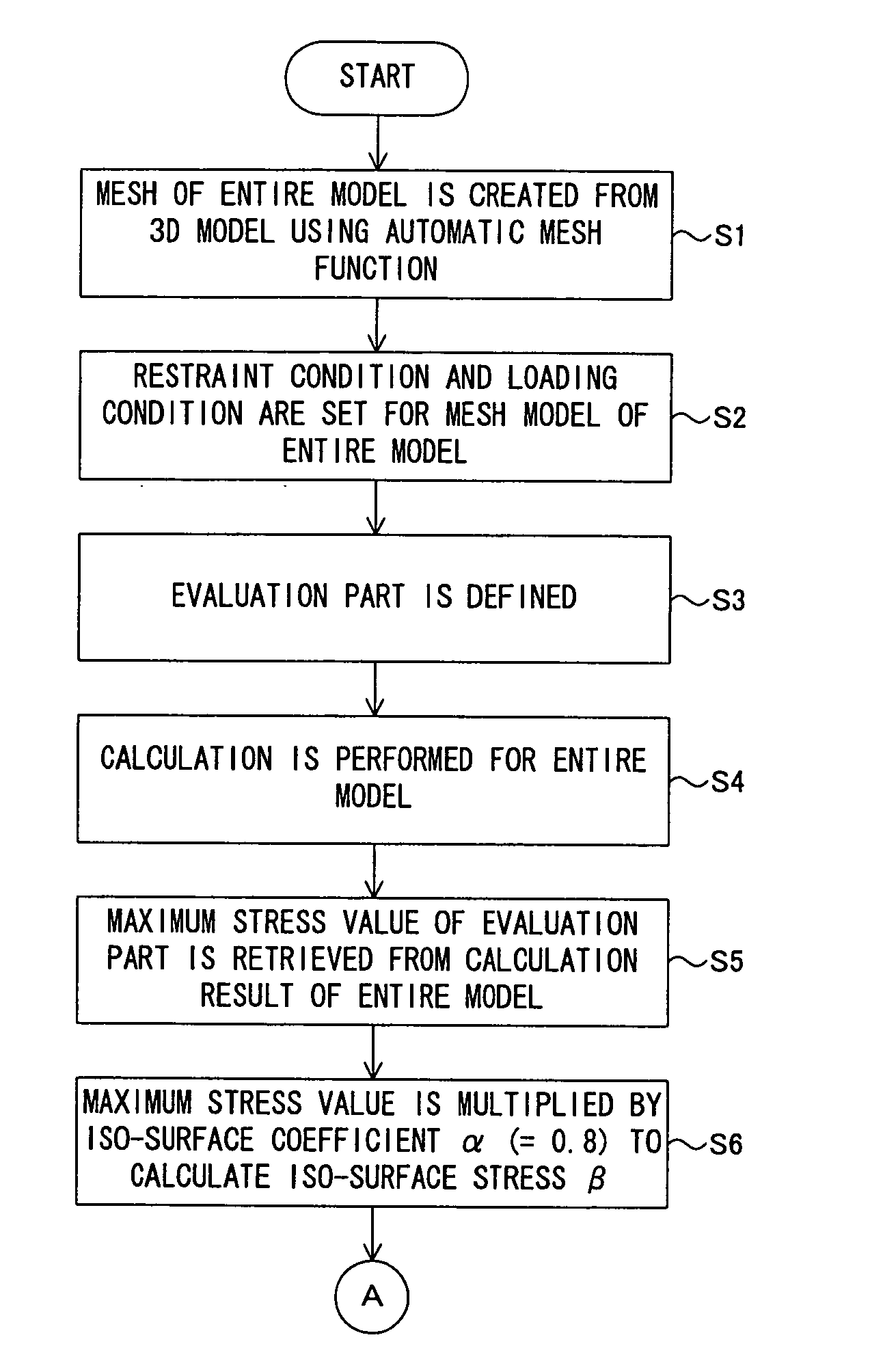
On the other hand, in the case where a part to be actually evaluated in a to-be-modeled area is very small due to limitation of a restraint condition or loading condition, if the entire evaluation part is divided into meshes of very small size for sufficient evaluation, a calculation amount becomes huge.
Further, it is difficult to determine whether the result obtained in the detailed model is sufficiently accurate or not, so that recalculation must be made using the detailed mesh model for verification, causing a lot of trouble.

Method used


Image

  • Structural analysis apparatus, structural analysis method, and structural analysis program
  • Structural analysis apparatus, structural analysis method, and structural analysis program
  • Structural analysis apparatus, structural analysis method, and structural analysis program

Examples


Embodiment Construction

[0035]An embodiment of the present invention will be described below with reference to the accompanying drawings.

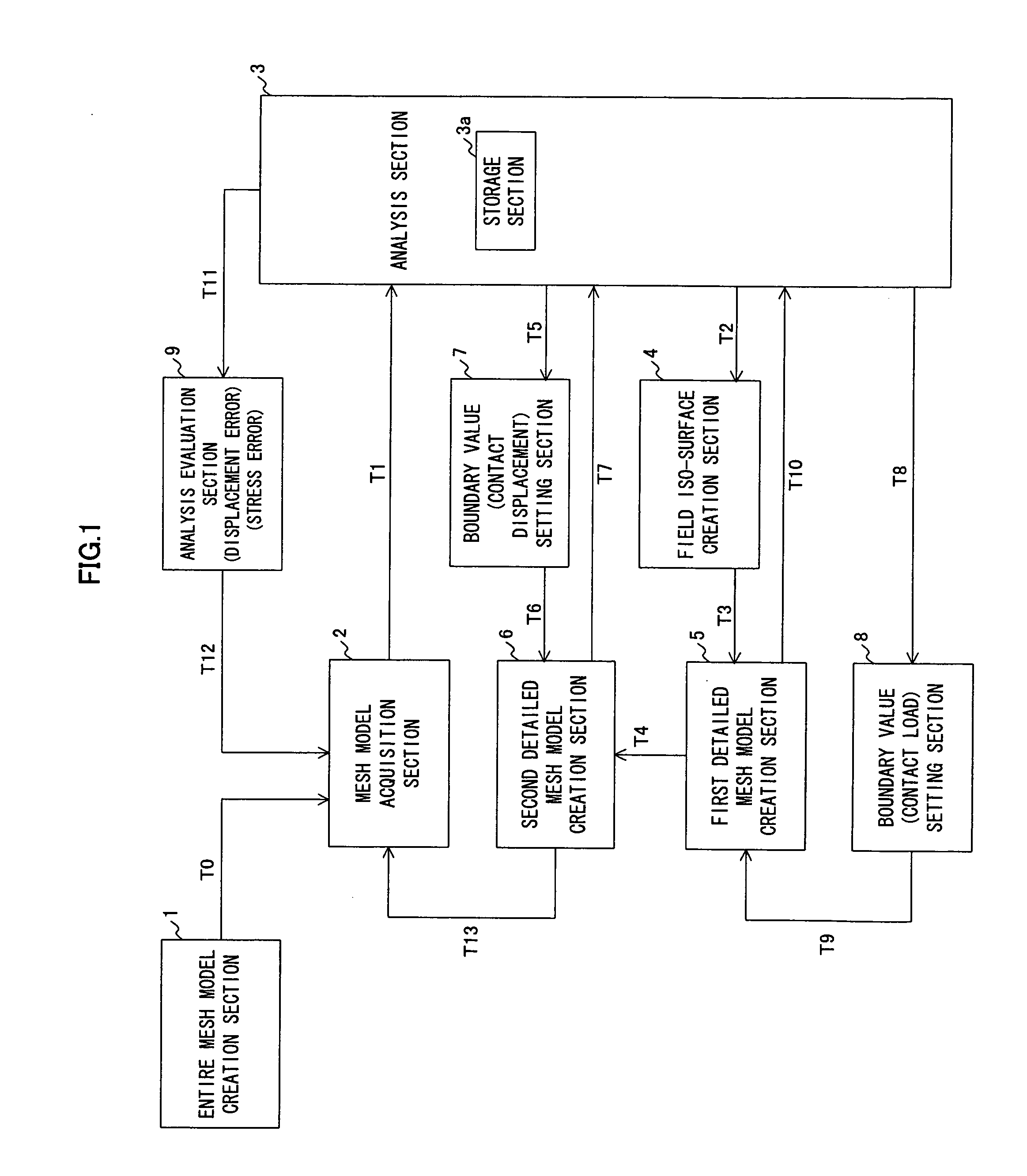
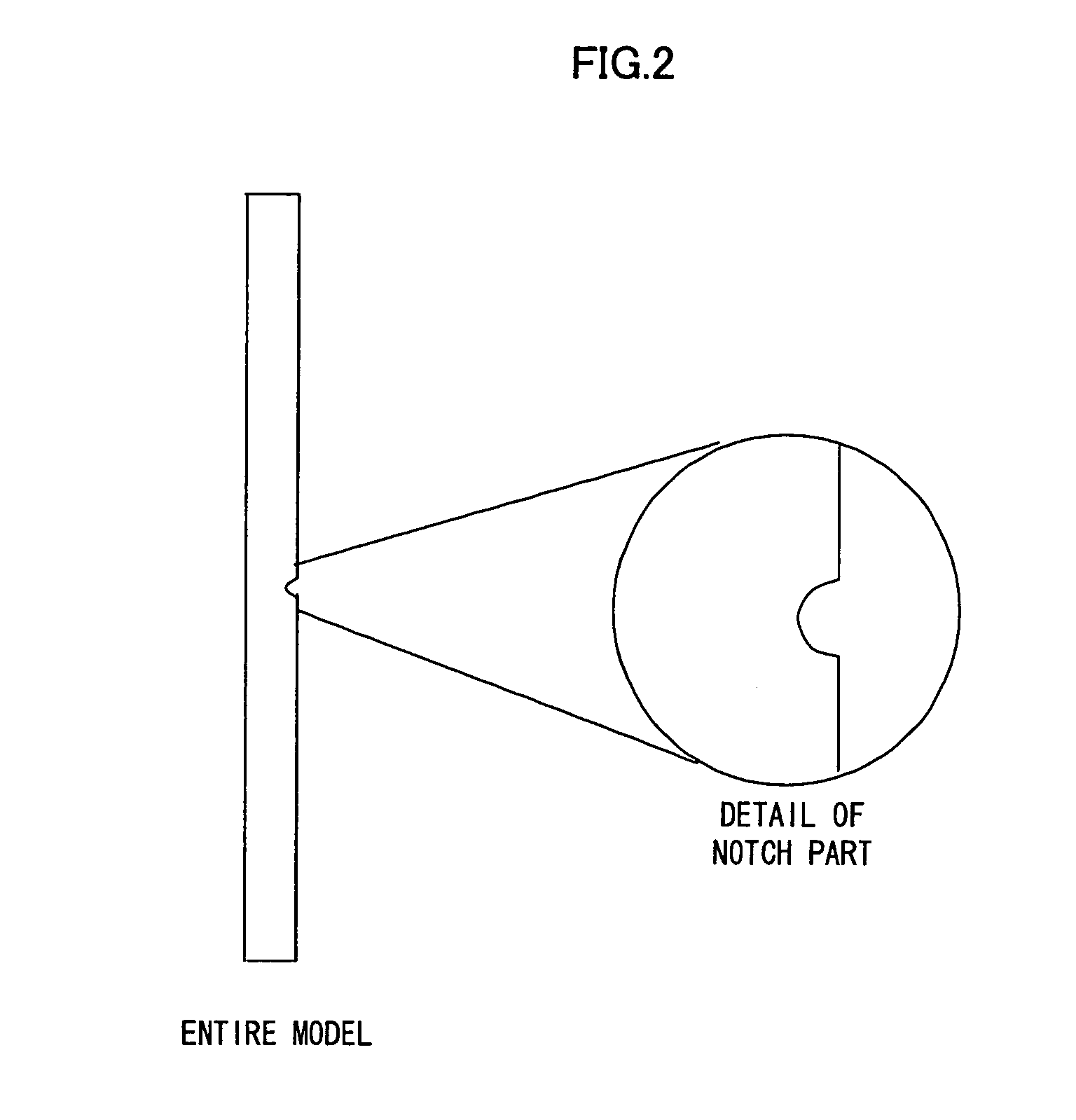
[0036]FIG. 1 is a block diagram showing the entire configuration of a structural analysis apparatus according to an embodiment of the present invention. FIG. 2 is an overall view of a model to be analyzed (prism model with a minute notch) and partially detailed view thereof. FIG. 3 is a conceptual view showing a process of sequentially creating a detailed mesh model from an entire model (mesh model).

[0037]As shown in FIG. 1, a structural analysis apparatus according to the present embodiment includes an entire mesh model creation section 1 that creates an entire mesh model from its original entire model and a mesh model acquisition section 2 that acquires the mesh model created by the entire mash model creation section 1 (T0). The entire mesh model creation section 1 and mesh model acquisition section 2 may be integrated in one component.

[0038]The structural analysis appa...


PUM


Abstract

There is provided a structural analysis apparatus capable of automatically setting the boundary between the entire model and detailed model to thereby obtain a highly accurate solution without intervention of an operator and with less man-hour and less calculation time.A structural analysis method comprises: an iso-surface creation step that creates a field iso-surface from an analysis result of a mesh model; a detailed mesh model creation step that uses the field iso-surface created by the iso-surface creation step to create a detailed mesh model of a part of the mesh model; an analysis step that uses the analysis result of the mesh model to perform analysis of the detailed mesh model created by the detailed mesh model creation step; and an analysis evaluation step that evaluates the analysis result of the detailed mesh model based on the analysis result obtained by the analysis step and analysis result of the mesh model.

Description

BACKGROUND OF THE INVENTION[0001]1. Field of the Invention[0002]The present invention relates to a numerical analysis method represented by a structure strength evaluation and, more particularly, to a structural analysis apparatus, a structural analysis method, and a structural analysis program that evaluate the strength of a structure in a development process of, e.g., a portable electronic device.[0003]2. Description of the Related Art[0004]In structural simulation which is taken as an example of structural analysis, in the case where a maximum stress occurring when a load is applied to a structure is calculated, an accurate result cannot be obtained unless the mesh of a stress concentration zone is sufficiently dense. On the other hand, in the case where a part to be actually evaluated in a to-be-modeled area is very small due to limitation of a restraint condition or loading condition, if the entire evaluation part is divided into meshes of very small size for sufficient evaluat...

Claims


Application Information

Patent Timeline
IPC IPC(8): G06F17/10G01M99/00
CPCG06T17/20G06F17/5018G06F30/23
Inventor ISHIKAWA, SHIGEO
Owner FUJITSU LTD
Learn More