Tunable optical add/drop multiplexer

a multiplexer and optical technology, applied in multiplex communication, instruments, optical elements, etc., can solve the problems of affecting the quality of service, and intermittent data loss from those intermediate wavelength channels

Active Publication Date: 2007-10-04
LUMENTUM OPERATIONS LLC
View PDF12 Cites 21 Cited by
  • Summary
  • Abstract
  • Description
  • Claims
  • Application Information

AI Technical Summary

Problems solved by technology

The key issue of the technology for rotating tunable filters and TOADMs is how to control the angle and the position of the reflected and transmitted optical beams, when they pass through or are reflected by the TFF.
Unfortunately, the mirror and the TFF need to be rotated simultaneously, necessitating a transmissive mounting block assembly supporting the mirror and the TFF, and a highly accurate alignment process.
However, one unfortunate aspect resulting from dynamically tuning an add / drop device is that intermediate wavelength channels, those channels having wavelengths existing between that of the initially tuned channel and that of the finally tuned channel, will each sequentially exhibit a temporary loss of signal continuity as the filter is tuned to each respective channel's wavelength.
When the composite optical signal light strikes filter locations corresponding to intermediate wavelength channels, intermittent data loss from those intermediate wavelength channels results.
Ultimately, such data loss results in diminished quality of service, decreased bandwidth efficiency, or both

Method used


Image

  • Tunable optical add/drop multiplexer
  • Tunable optical add/drop multiplexer
  • Tunable optical add/drop multiplexer

Examples


first embodiment

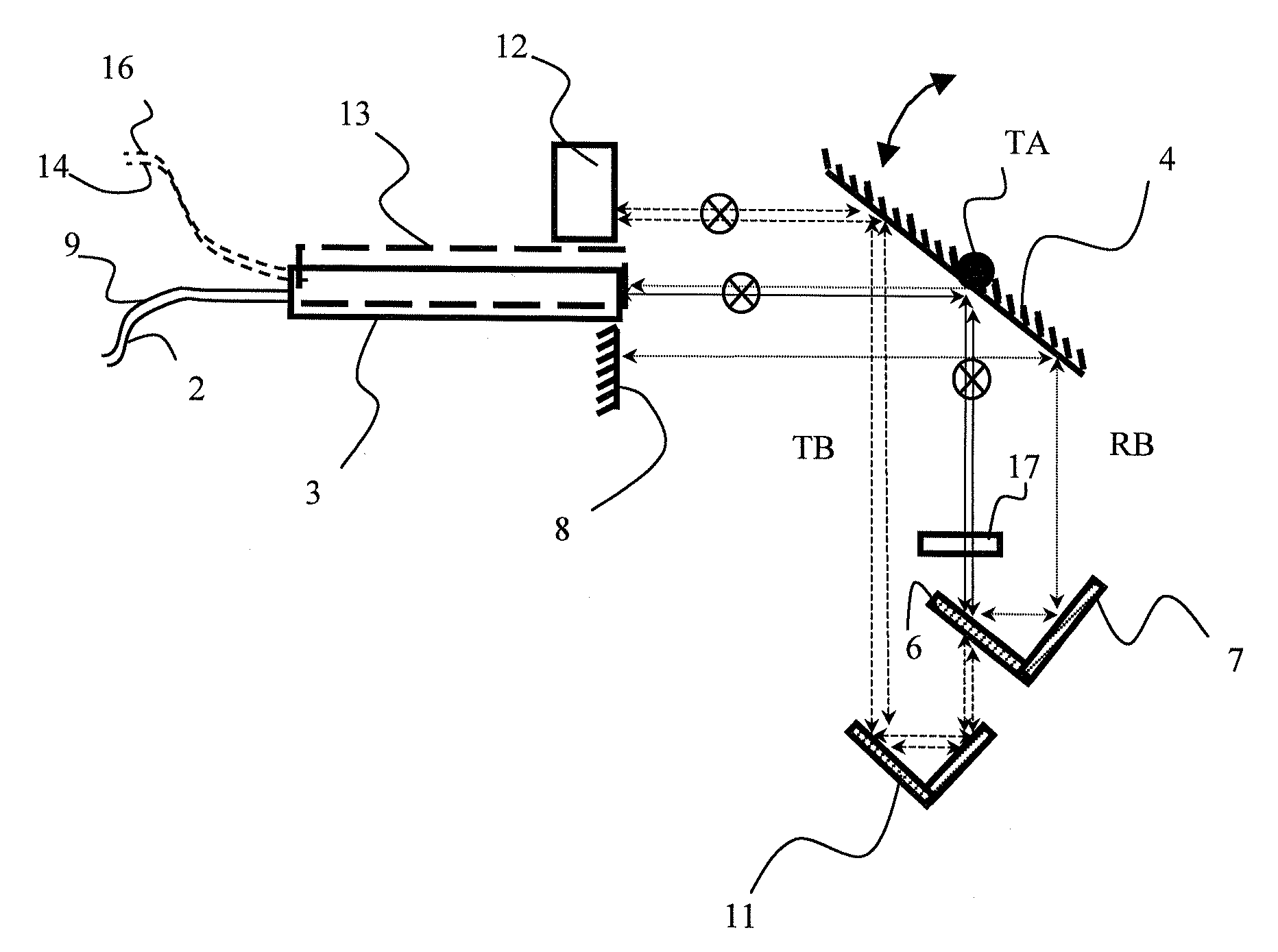
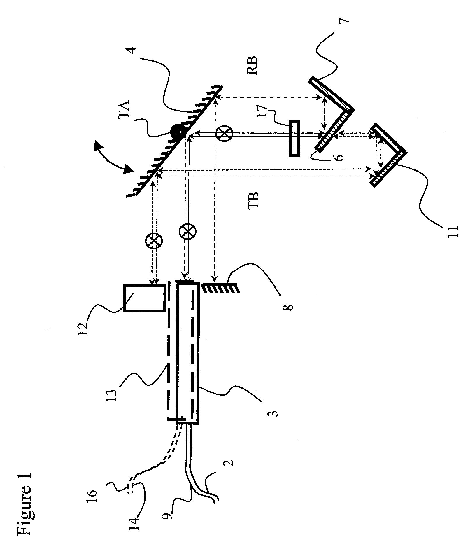
[0050]The apparatus of a first embodiment illustrated in FIG. 14 comprises a tiltable mirror 64 with a tilting axis TA, a first fixed angled mirror 65, a second fixed angled mirror 66, and a third fixed end mirror 67, similar to the elements used in the embodiment of FIG. 1 for the reflect beam RB. An input beam launched from an input / output port 68 is incident on the tiltable mirror 64 along the tilting axis TA, and is reflected to the first fixed mirror 65 with an initial angle of reflection. The first fixed mirror 65 reflects the beam to the second fixed mirror 66, which reflects the beam back to the tiltable mirror 64 at a position adjacent to the tilting axis TA. The tiltable mirror 64 reflects the beam a second time to the third fixed mirror 67.

[0051]The angle of the beam arriving at the third fixed mirror 67 remains unchanged, i.e. 0° to the normal of the third fixed mirror 67 or perpendicular to the face of the third fixed mirror 67, even while the tiltable mirror 64 is rota...

second embodiment

[0054]the present invention is illustrated in FIG. 15, wherein the tiltable mirror 65, the first fixed mirror 66 and the second fixed mirror 67 are generally the same as above, but the third fixed mirror is replaced by a vertically (into the page) arranged retro-reflector 71, which enables the beam be laterally shifted a certain amount into a different, parallel plane, e.g. parallel with the plane of the page, so that reflected beam does not go back to the input / output port 68, but an adjacent input / output port 78, similar to the elements used in the embodiment of FIG. 1 for the transmit beam TB. The amount of displacement is determined by the position of the retro-reflector 71, providing a desired or required separation between the input and reflected beam(output). The retro-reflector 71 comprises two perpendicular mirror plates, whose cross line is perpendicular to the beam incident thereon.

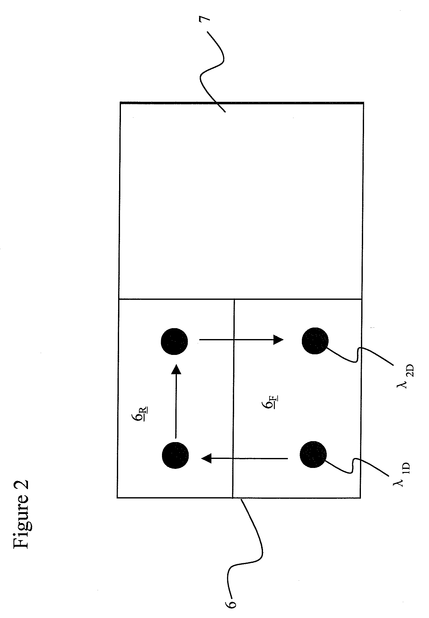
[0055]FIG. 16 illustrates a more compact embodiment in which the first and second fixed mir...


PUM


Abstract

The tunable add / drop multiplexer including a tiltable mirror, a fixed thin film filter, and first and second retro-reflector elements for redirecting express channels back out an input / output port and for redirecting drop channels back out an add / drop port, respectively.

Description

CROSS-REFERENCE TO RELATED APPLICATIONS[0001]The present invention claims priority from U.S. patent application Ser. No. 60 / 744,205 filed Apr. 4, 2006, which is incorporated herein by reference for all purposes.TECHNICAL FIELD[0002]The present invention relates to a tunable optical add / drop multiplexer (TOADM), and in particular to a TOADM utilizing a tiltable mirror and a fixed thin film filter.BACKGROUND OF THE INVENTION[0003]Tunable optical add / drop multiplexers (TOADM) or reconfigurable optical add / drop multiplexers (ROADM) are an integral part of next generation optical networks, and they are the building blocks of Agile Optical Networks, because they provide the flexibility to remotely tune or reconfigure any or all wavelengths, thereby reducing time-to-service, simplifying the network, and streamlining planning and management.[0004]The basic requirements for TOADM's or ROADM's are: flat-top filter characteristic for drop / add function, low insertion loss in express channels, n...

Claims


Application Information

Patent Timeline
IPC IPC(8): G02B6/28G02B6/34
CPCG02B6/2713G02B6/2746G02B6/2766G02B6/359G02B6/29383G02B6/29395G02B6/3512G02B6/29362
Inventor CHEN, BOCAI, BOYANG, YATAOLIANG, MINGWANG, XIAOBIAO
Owner LUMENTUM OPERATIONS LLC
Why Eureka
Try Eureka