Loop locating apparatus and loop locating method in layer 3 network

a technology of loop locating and loop locating, which is applied in the field of loop locating apparatus and loop locating method, can solve the problems of enormous multicast traffic, failure to set routing information for information packets, and enormous time required for identifying the location, and achieves the effect of fast and simple techniqu

Inactive Publication Date: 2007-10-04
FUJITSU LTD
View PDF10 Cites 14 Cited by
  • Summary
  • Abstract
  • Description
  • Claims
  • Application Information

AI Technical Summary

Benefits of technology

[0012]An object of the present invention is to provide a fast, simple technique f...

Problems solved by technology

A leading cause of such a “loop” is an error in setting of the equipment in the routing tables in the two routers and the consequent failure of setting routing information for the information packets.
Also, the multicast traffic will therefore become enormous.
Accordingly, since the method of se...

Method used


Image

  • Loop locating apparatus and loop locating method in layer 3 network
  • Loop locating apparatus and loop locating method in layer 3 network
  • Loop locating apparatus and loop locating method in layer 3 network

Examples


Embodiment Construction

[0032]Preferred embodiments of the present invention will be described in detail below while referring to the attached figures.

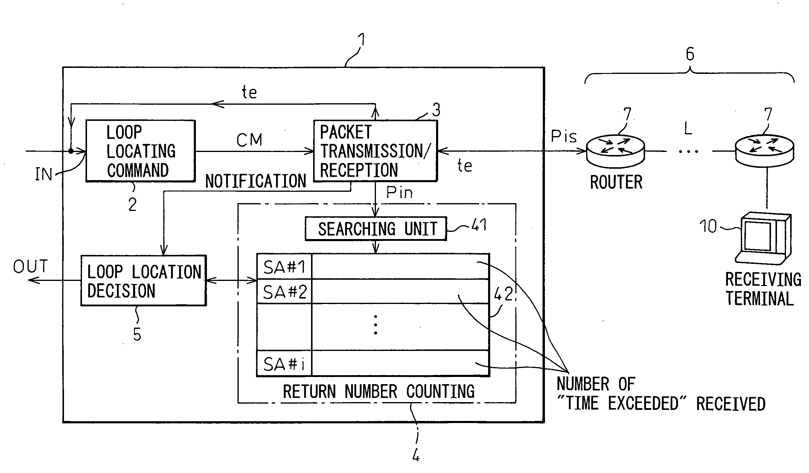
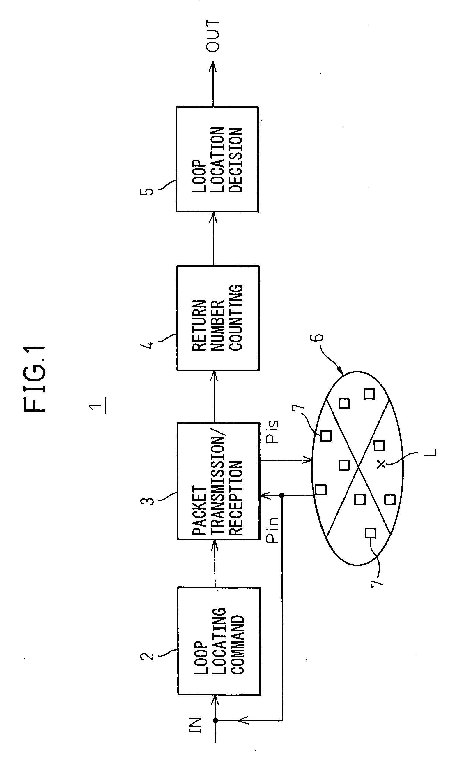
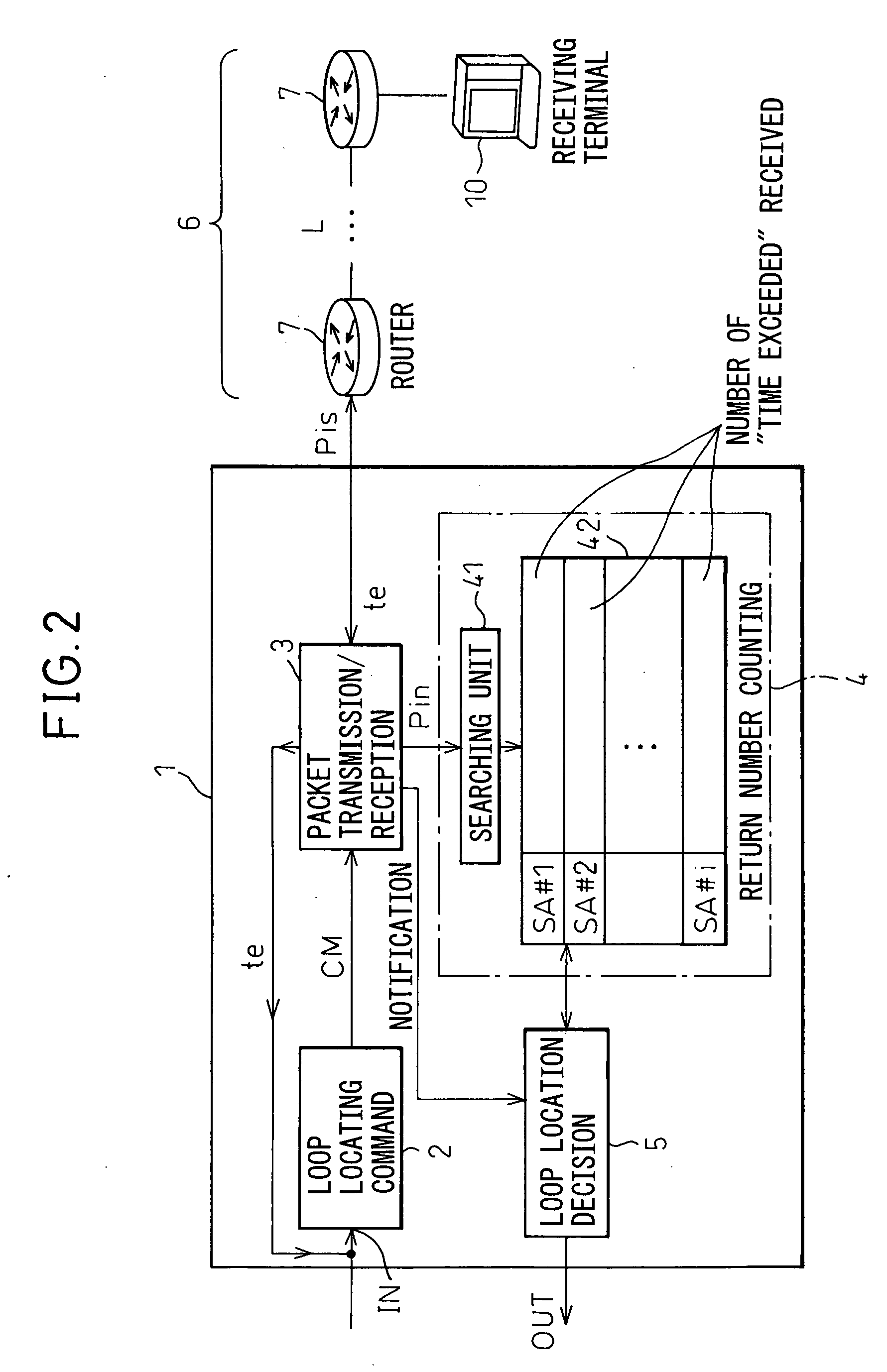
[0033]FIG. 1 is a view of the basic configuration of a loop locating apparatus according to the present invention. In the figure, reference numeral 1 indicates a loop locating apparatus according to the present invention. As illustrated, this is comprised of a loop locating command function unit 2, a packet transmission / reception function unit 3, a return number counting function unit 4, and a loop location decision function unit 5. Among these function units, the packet transmission / reception function 3 is linked with a Layer 3 network 6. The network 6 has a plurality of routers 7.

[0034]That is, the loop locating apparatus 1 according to the present invention is an apparatus for identifying the location of a Layer 3 loop occurring in a Layer 3 network 6 including a plurality of routers 7. Here, the functions of the function units 2 to 5 are as follows:

[...


PUM


Abstract

A loop locating apparatus and method enabling simple and fast identification of a Layer 3 loop fault occurring in a network, wherein, when the possibility of a Layer 3 loop is detected, a loop locating command function unit makes a packet transmission/reception function unit send a series of inspection packets (Pis) with successively incremented TTLs and monitors the return packets (te) of the inspection packets (Pis) by a return number counting function unit and wherein a loop location decision function unit finds the routers returning packets (te) with remarkably larger return numbers than the others and identifies the routers with return numbers over a predetermined threshold as the location of occurrence of the loop.

Description

BACKGROUND OF THE INVENTION[0001]1. Field of the Invention[0002]The present invention relates to a loop locating apparatus and loop locating method for identifying a location of occurrence of a fault occurring in an IP (Internet Protocol) network, for example, an IP Multicast Layer 3 Network including a plurality of routers, in particular a Layer 3 loop fault.[0003]2. Description of the Related Art[0004]As will be explained later with reference to the figures (FIG. 16), in an IP Multicast Layer 3 Network, sometimes a Layer 3 loop fault (hereinafter referred to simply as a “loop”) occurs. This “loop” means the situation, when transmitting information packets by multicasting from one terminal to a plurality of terminals in a Layer 3 Network, where information packets end up traveling back and forth in a loop between two adjoining routers of the plurality of routers and are no longer forwarded to the terminals further on.[0005]A leading cause of such a “loop” is an error in setting of ...

Claims


Application Information

Patent Timeline
IPC IPC(8): H04J3/14H04L12/70
CPCH04L41/0677H04L43/10H04L45/00H04L45/02H04L47/10H04L45/18H04L45/20H04L45/26H04L45/28H04L45/16
Inventor NISHI, TETSUYAGOTOH, TOMONORI
Owner FUJITSU LTD
Why Eureka
Try Eureka