
Removable device

a technology of a removable device and a body is applied in the field of removable devices, which can solve the problems of increased fabrication costs, complicated assembly process, and huge storage space of the servo device, and achieve the effects of reducing manufacturing costs, simplifying the constituent components, and reducing assembly costs

Active Publication Date: 2007-10-04
INVENTEC CORP
View PDF19 Cites 19 Cited by
  • Summary
  • Abstract
  • Description
  • Claims
  • Application Information

AI Technical Summary

Benefits of technology

[0011] Another objective of the present invention is to provide a removable device of which assembly is fast and simple.
[0021] In short, the removable device of the present invention can overcome the drawbacks of conventional removable devices and thereby is highly industrial applicable.

Problems solved by technology

A servo device needs enormous storage space, thus it is typically equipped with a plurality of removable hard disk cartridges for holding hard disks.
Nevertheless, the aforesaid prior art has a drawback of having too many constituent elements, which results in a complicated, time-consuming assembly process.
Furthermore, an excessively great number of constituent elements also means increased fabrication costs.

Method used


Image

  • Removable device
  • Removable device
  • Removable device

Examples


Embodiment Construction

[0028] The following specific embodiments are provided to illustrate the present invention. Others skilled in the art will readily understand other advantages and functions of the present invention in accordance with the contents disclosed in this specification. The present invention can also be performed or applied by other different embodiments. Various modifications and changes based on different viewpoints and applications can be made in the details of the specification without departing from the spirit of the present invention.

[0029] It should be noted that the drawings are simplified schematic diagrams and only show components relating to the present invention. In practice, the layout of the components may be far more intricate.

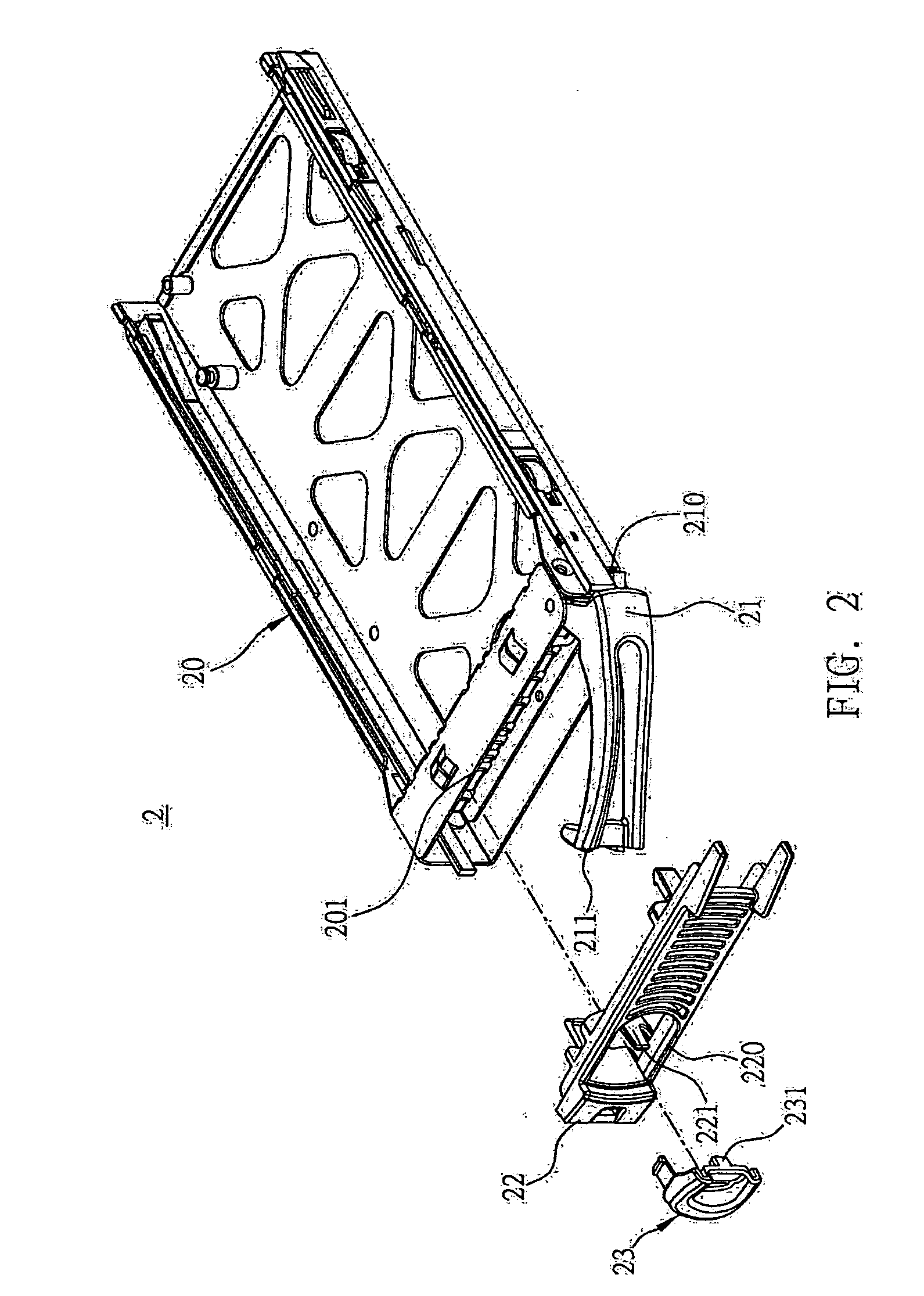
[0030]FIG. 2 shows an exploded view of a preferred embodiment for a removable device of the present invention. The removable device 2 of the present invention comprises a body 20, a removing handle 21, a panel 22, and a snap-fit element 23. The removi...


PUM


Abstract

A removable device is proposed, which includes a body, a removing handle, a panel, and a snap-fit element. The removing handle has one end pivotally connected to one side of the body and the other end formed with a snap-fit portion. The panel is disposed on the side of the body and is provided with an installation hole and an elastic portion located at the installation hole. The snap-fit element is installed in and partly covers the installation hole, for snap-fit engagement with the snap-fit portion of the removing handle. The snap-fit element includes an extending portion pressing against the elastic portion, such that the elastic portion provides the snap-fit element with the elasticity required to move in relation to the installation hole. Accordingly, the above removable device solves the drawbacks of complicated numerous constituent components of a conventional removable device.

Description

BACKGROUND OF THE INVENTION [0001] 1. Field of the Invention [0002] This invention relates to a removable device, and more particularly, to a removable device having a removing handle. [0003] 2. Description of Related Art [0004] Removable devices have been widely used in servo devices and personal computers. A servo device needs enormous storage space, thus it is typically equipped with a plurality of removable hard disk cartridges for holding hard disks. Each removable hard disk cartridge is hot-swappable, and it is swiftly replaced if necessary. [0005] The removable hard disk cartridge is typically inserted into and thereby held in a slot of the servo device. It is pivotally connected to a removing handle having one end fixed to the servo device and the opposing end adapted for snap-fit engagement with the removable hard disk cartridge. This, coupled with the holding of the removable hard disk cartridge by the slot of the servo device, secures the removable hard disk cartridge in ...

Claims


Application Information

Patent Timeline
Patent Type & Authority Applications(United States)
IPC IPC(8): G06F1/16
CPCG06F1/18G11B33/124G11B33/12
Inventor HSU, YUNG-CHINYANG, SHENG-TZU
Owner INVENTEC CORP
Learn More