Interlocked hydrogen source for gas chromatography

Inactive Publication Date: 2007-09-27
AGILENT TECH INC
View PDF2 Cites 15 Cited by
  • Summary
  • Abstract
  • Description
  • Claims
  • Application Information

AI Technical Summary

Benefits of technology

[0006] A gas chromatograph (GC) uses hydrogen carrier gas from a hydrogen source. The hydrogen source is in communication with the GC. An hydrogen sensor is capable of detecting the level of hydrogen in the ambient environment in which the system operates. The hydrogen sensor could also be located within the GC instrument itself. When the levels of hydrogen exceed an acceptable threshold, the GC shuts down the hydrogen source to stop the flow of hydrogen. Shutdown of the hydrogen source is also possible for other unsafe or “not-ready” conditions of the GC and its detection system.

Problems solved by technology

But, there are several drawbacks to using helium as a carrier gas.
For example, the helium is an element and as such the supply is inherently limited.
Helium can be expensive, especially in countries outside of the United States.
Also, helium is stored in large, heavy tanks that are unwieldy to transport.
Furthermore, the tanks may become dangerous projectiles if dropped or mishandled due to the highly compressed nature of the helium inside.
Finally, there is some unwanted overlap between sample (compound) bands when helium is used as the carrier gas due to limitations on the resolving power in chromatographic separations using helium.
Despite all these advantages, there is hesitance to adopt hydrogen as a carrier gas due to its high combustibility and potential for explosion.

Method used


Image

  • Interlocked hydrogen source for gas chromatography
  • Interlocked hydrogen source for gas chromatography
  • Interlocked hydrogen source for gas chromatography

Examples


Embodiment Construction

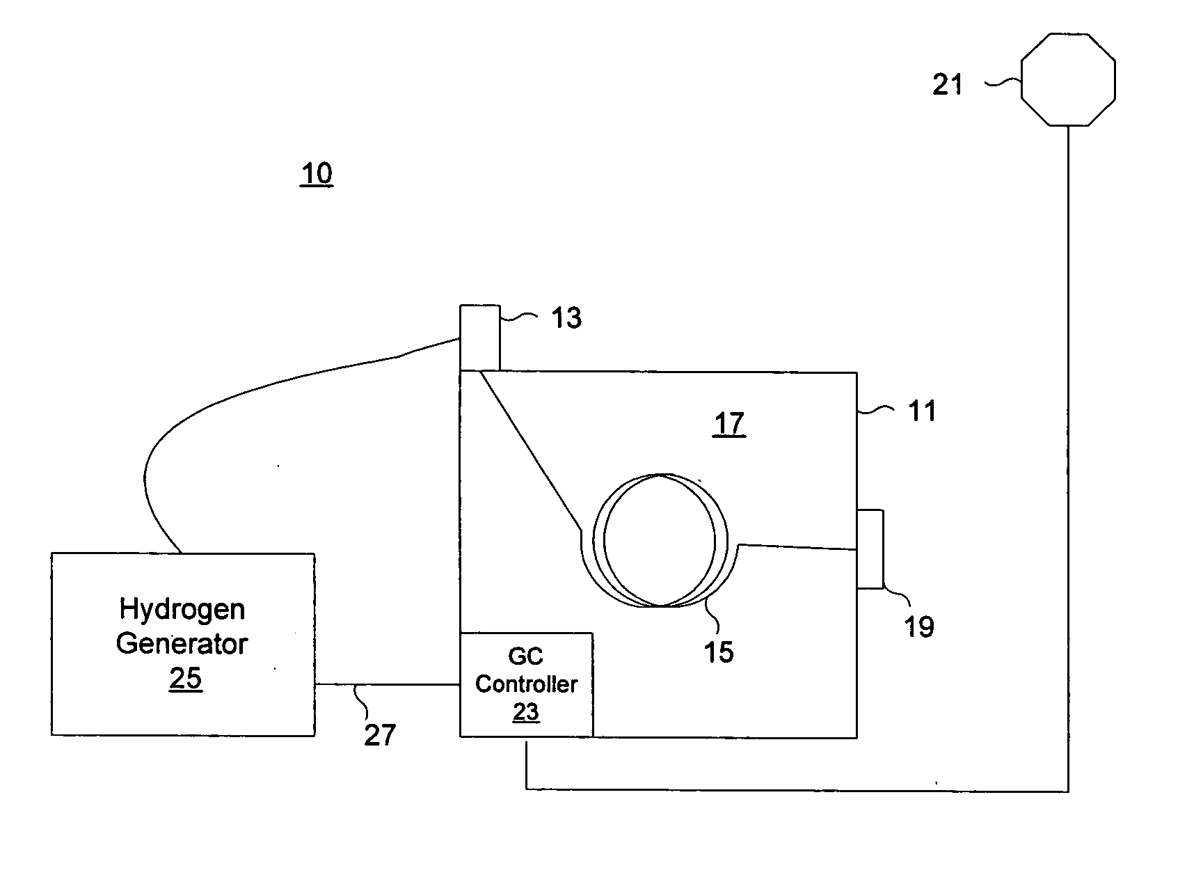
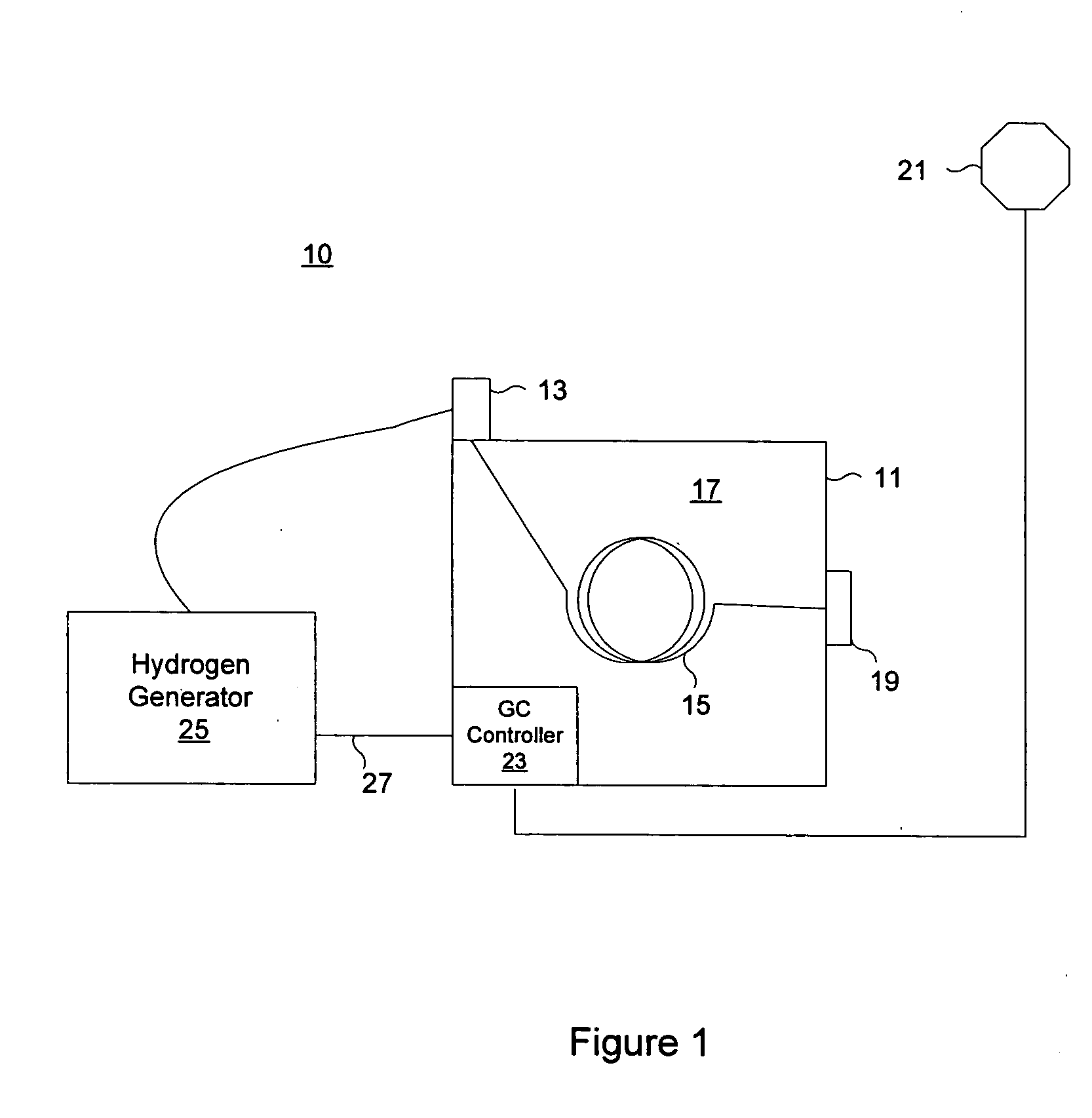
[0009]FIG. 1 shows a preferred embodiment of a gas chromatography system 10 made in accordance with the teachings of the present invention. The gas chromatography system 10 includes a gas chromatograph (GC) 11, a hydrogen generator 25, a hydrogen sensor 21, and a detector 19. The GC 11 has an injector 13 that injects a sample into a column 15. The column 15 is contained in a temperature-controlled oven 17. A GC controller 23 is the internal “brain” (e.g. a CPU or microprocessor) that runs the GC 11. It controls details such as the oven temperature, the injection of an analyte, the flow rate of the carrier gas, etc. Not shown in the drawing are the appropriate exhaust lines for hydrogen from such devices as the split port of the GC, or the mass spectrometer pumping system exhaust port, or other places germane to the specific GC and detector configurations.

[0010] A hydrogen generator 25 generates hydrogen gas from deionized water. Typically, the hydrogen generator 25 produces hydroge...


PUM


Abstract

A gas chromatograph uses hydrogen carrier gas supplied by a hydrogen source. At least one hydrogen sensor monitors the hydrogen level. The gas chromatograph communicates with the hydrogen source over a communication link. When the sensed hydrogen level exceeds a threshold, the gas chromatograph signals the hydrogen source to stop the flow of hydrogen.

Description

BACKGROUND OF THE INVENTION [0001] Gas chromatography is a technique used to analyze a sample consisting of a mixture of compounds. A gas chromatograph separates a sample into its individual compounds, and is used in combination with a suitable detector to identify and measure those individual compounds. [0002] The gas chromatograph relies on a carrier gas to carry the sample and its component compounds through a heated column. The sample compounds vaporize within the column, and travel through the column at different rates, depending on the physical properties of the compounds and their interaction with the column phase, etc. For instance, smaller molecules generally move through the column quicker than larger molecules basically due to their higher volatility. All of the molecules corresponding to a specific compound travel through the column at nearly the same rate and appear as a band of molecules (called a chromatographic peak) at the detector such as a mass spectrometer. Ideal...

Claims


Application Information

Patent Timeline
IPC IPC(8): G01N30/02
CPCG01N30/34G01N2030/8804G01N2030/342G01N2030/025
Inventor PREST, HARRY F.
Owner AGILENT TECH INC
Why Eureka
Try Eureka