
Fastening element

a technology of fastening elements and fastening elements, which is applied in the direction of fastening means, dowels, mechanical equipment, etc., can solve the problems of reducing the range of holding values of fastening elements, characterized by higher failure loads, and characterized by the inventive fastening element having a smaller variance of holding values, so as to facilitate the formation of furrows. , the effect of improving the introduction of the resulting

Inactive Publication Date: 2007-09-27
HILTI AG
View PDF0 Cites 20 Cited by
  • Summary
  • Abstract
  • Description
  • Claims
  • Application Information

AI Technical Summary

Benefits of technology

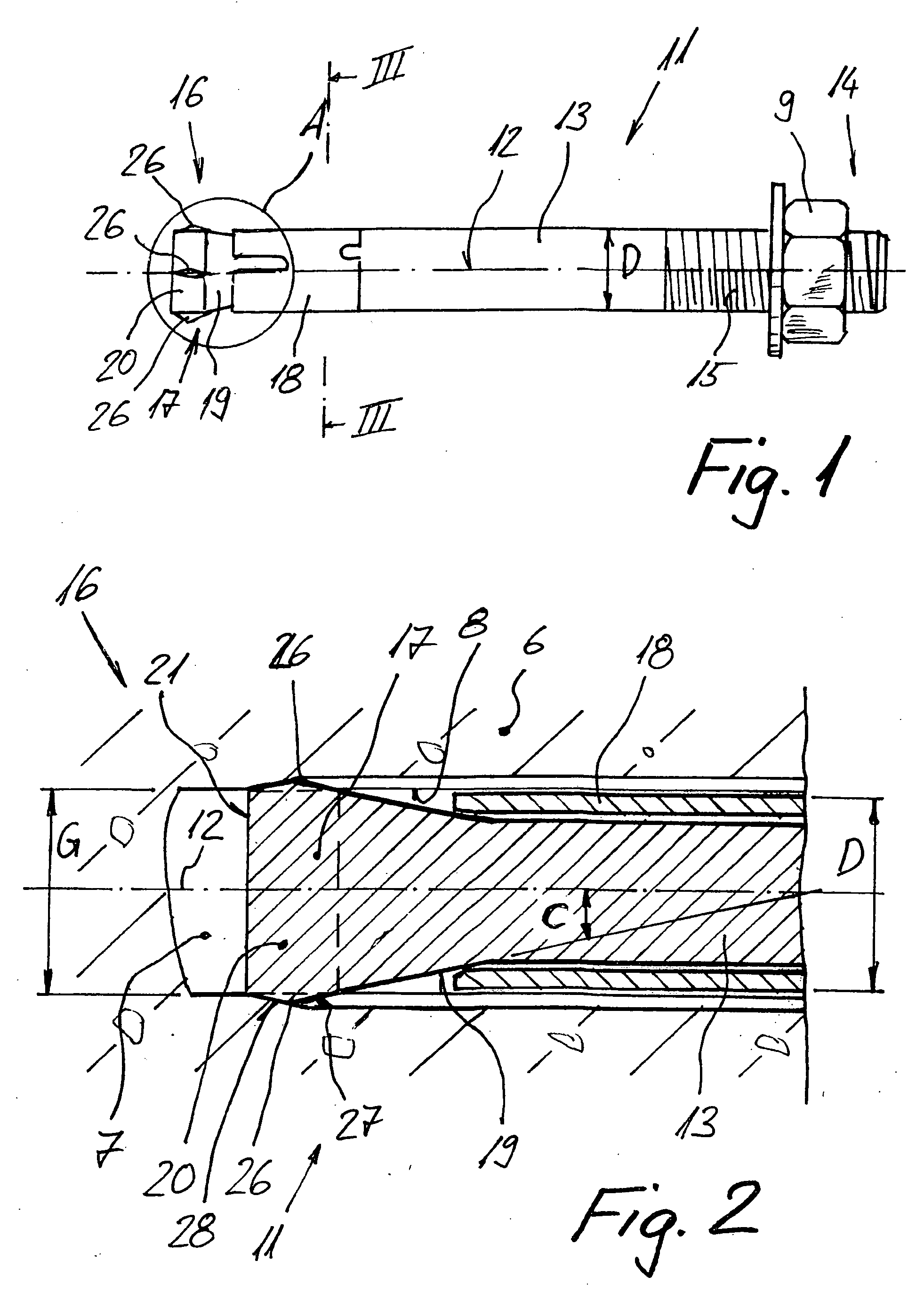
[0015]The projection of the ribs beyond the axial projection of the outer profile of the expansion sleeve over the circumference of the expansion sleeve is advantageously so selected that during driving of the fastening element in the borehole, the ribs furrow the borehole wall. The produced force-and formlocking connection of the expansion portion with the borehole wall prevents rotation of the fastening element in the borehole and facilitate centering of the expansion portion and, thereby, of the entire fastening element in the borehole. The prevention of rotation of the fastening element, which is obtained with the ribs, also reduces the tendency of the fastening element to rotate when a heavy-duty thread is used as the load application means, which is often the case under constructional site conditions.
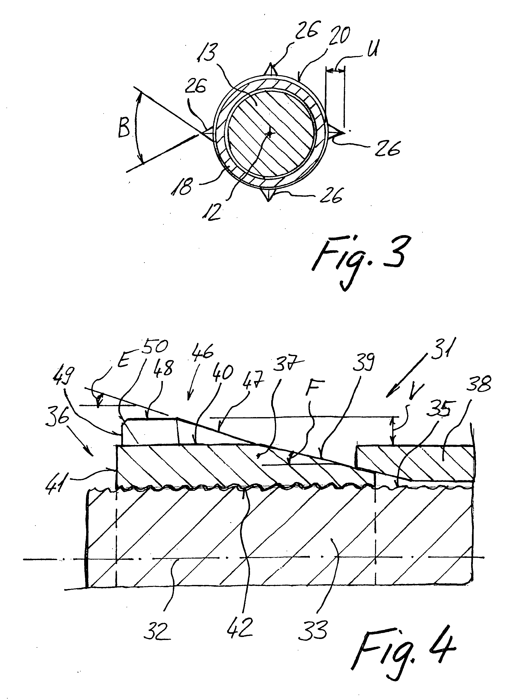
[0026]Alternatively, the second edge extends parallel to the longitudinal axis of the fastening element, and a third edge adjacent to the free end of the fastening element extends transverse to the longitudinal axis. The third edge is also advantageously formed as a sharp cutting edge. In order to facilitate the setting of the fastening element, the corner between the second and third edges is advantageously chamfered. This embodiment of the ribs is easily formed, which enables an easy and cost-effective manufacturing of the inventive fastening element.

Problems solved by technology

Therefore, the inventive fastening element is characterized by higher failure loads than a conventional fastening element and has a smaller variance of holding values.

Method used


Image

  • Fastening element
  • Fastening element
  • Fastening element

Examples


first embodiment

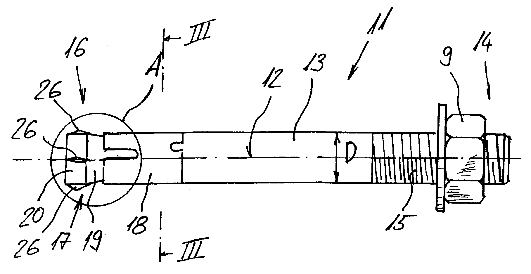
[0034]A fastening element 11 according to the present invention, which is shown in FIGS. 1-3 and which is designed for being anchored in a borehole 7 of a constructional component 6, includes an anchor bolt and an expansion sleeve 18. The anchor bolt has a stem 13 having a longitudinal axis 12. The stem 13 has a first end region 14 at which there is provided load application means 15, and a second opposite end region 16 at which there is provided an expansion portion 17 for expanding the expansion sleeve 18 that at least partially surrounds the stem 13. The expansion portion (17) has a conical section 19 that expands toward the free end of the stem 13, and a cylindrical section 20 that adjoins the conical section 19 and has a certain profile. The conical section 19 is located adjacent to the expansion sleeve 18.

[0035]The profile on the cylindrical section 20 of the expansion portion 17 is formed by four ribs 26 extending parallel to the longitudinal axis 12 of the stem 13 and projec...

second embodiment

[0038]a fastening element according to the present invention and which is designated with a reference numeral 31, is shown in FIG. 4. The fastening element 31 has a stem 33 which is formed as a threaded rod with an outer thread 35 that extends over an entire longitudinal extent of the stem 33 parallel to the longitudinal axis 32 of the stem 33. At the first end region of the stem 33, the outer thread 35 forms load application means at the second opposite end region 36 of the stem 33, there is provided a cone sleeve with an inner thread 42 and which forms an expansion portion 37 for expanding an expansion sleeve 38 which at least partially surrounds the stem 33. The cone sleeve with the inner thread 42 is screwed on the threaded rod that forms the stem 33. The expansion portion 37 has a conical section 39 that expands in the direction of the free-end of the second end region 36, and cylindrical section 40 that adjoins the conical section 39 and has a shaped profile.

[0039]The profile ...


PUM


Abstract

A fastening element for constructional components, includes an anchor bolt and an expansion sleeve (18, 38), with the anchor bolt having a load application element (15) at its first end region (14) of the anchor stem (13, 33), and at a second, opposite end region (16, 36) an expansion portion (17, 37) having a conical section (19, 39) that expands in a direction of a free end of the second end region, and a cylindrical section (20, 40) that adjoins the conical section (19, 39) and has a shaped profile formed by ribs (26, 46) extending parallel to the longitudinal axis (12, 32) of the stem with the ribs (26, 46), projecting beyond an axial projection of an outer profile of the expansion sleeve (18, 38) by a distance (U. V).

Description

BACKGROUND OF THE INVENTION[0001]1. Field of the Invention[0002]The present invention relates to a fastening element for being anchored in a borehole of a constructional component and including an anchor bolt and an expansion sleeve. The anchor bolt has a stem having a longitudinal axis and provided with load application means at its first end region and at its second, opposite end region with an expansion portion for expanding the expansion sleeve that at least partially surrounds the stem. The expansion portion has a conical section that expands in a direction of a free end of the second end region of the stem, and a cylindrical section that adjoins the conical section and has a shaped profile.[0003]2. Description of the Prior Art[0004]Fastening elements of the type described above serve for attachment of objects to a constructional component that has a borehole for receiving the fastening element. The fastening element becomes anchored as a result of a relative displacement betwe...

Claims


Application Information

Patent Timeline
IPC IPC(8): F16B13/06
CPCF16B13/065
Inventor AYRLE, THOMAS
Owner HILTI AG
Learn More