Power supply device with inrush current control circuit

a power supply device and control circuit technology, applied in the direction of emergency protective circuit arrangement, emergency protection arrangement for limiting excess voltage/current, etc., can solve the problem of inrush current generation and the shortened life of components

Inactive Publication Date: 2007-09-27
HON HAI PRECISION IND CO LTD
View PDF8 Cites 6 Cited by
  • Summary
  • Abstract
  • Description
  • Claims
  • Application Information

AI Technical Summary

Benefits of technology

[0003]The present invention provides a power supply device converting received power signals to direct current signals to a load. The power supply device includes a transformer circuit, a rectifier circuit, and an inrush current control circuit. The transformer circuit converts the received power signals to alternating current signals. The rectifier circuit is connected to the transformer circuit, and converts the alternating current signals to direct current signals. The inrush current control circuit is connected to the rectifier circuit, for limiting inrush current from the power supply device. The inrush current control circuit includes a voltage divider resistor and a filter capacitor. The filter capacitor is connected to the voltage divider resistor in series.

Problems solved by technology

However, when the power supply device is initially powered on, an inrush current is generated due to a capacitor effect.
Peak value of the inrush current can damage components, such as fuses, switches, so that life of the components is shortened accordingly.

Method used


Image

  • Power supply device with inrush current control circuit
  • Power supply device with inrush current control circuit
  • Power supply device with inrush current control circuit

Examples


Embodiment Construction

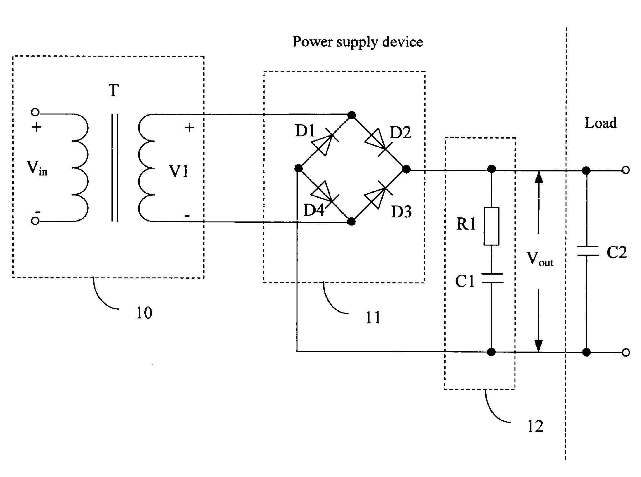
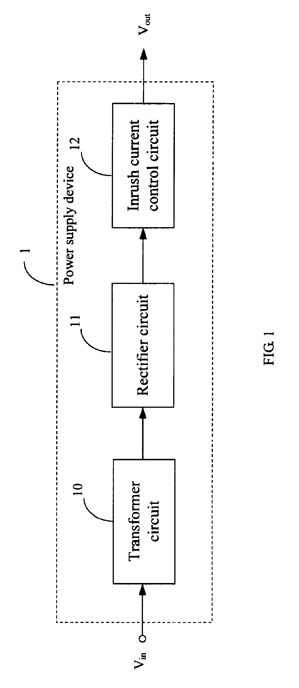
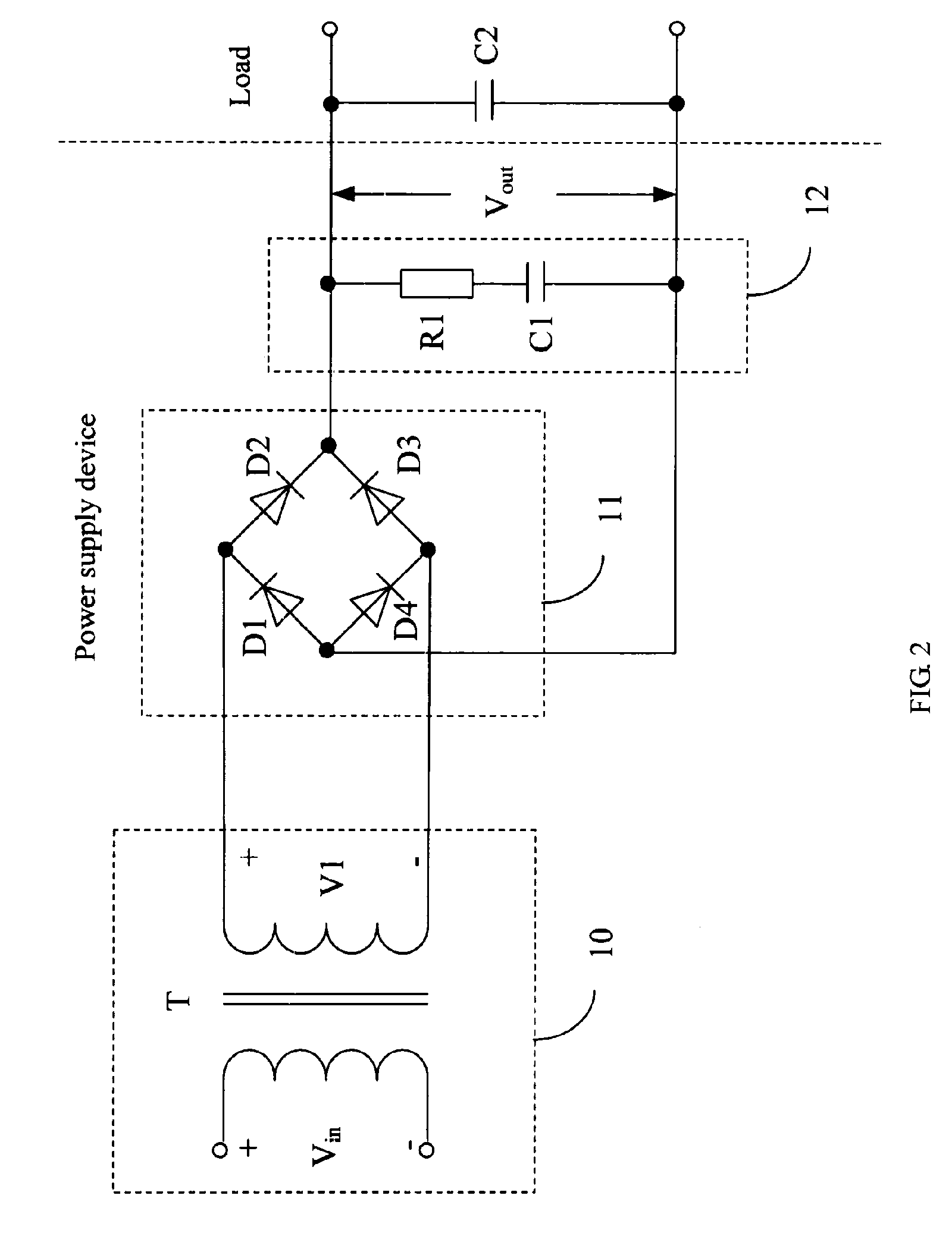
[0008]FIG. 1 is a block diagram of a power supply device 1 of an exemplary embodiment of the present invention. The power supply device 1 includes a transformer circuit 10, a rectifier circuit 11, and an inrush current control circuit 12.

[0009]The transformer circuit 10 converts received power signals Vin from a power source to alternating current (AC) signals. In the exemplary embodiment, the power signals Vin are sine-wave signals Vin output from an AC power source (for example, 220V in china, or 110V in USA, not shown in FIG. 1). The rectifier circuit 11 is connected to the transformer circuit 10, and converts the AC signals output from the transformer circuit 10 to direct current (DC) signals. In the exemplary embodiment, the DC signals are ripple signals. The inrush current control circuit 12 is connected to the rectifier circuit 11, for limiting inrush current from the power supply device 1 and filtering ripple from the DC signals, and outputting smooth DC signals Vout to a lo...


PUM


Abstract

A power supply device (1) converting received power signals to direct current signals to ensure a load to work normally. The power supply device includes a transformer circuit (10), a rectifier circuit (11), and an inrush current control circuit (12). The transformer circuit converts the received power signals to alternating current signals. The rectifier circuit is connected to the transformer circuit, and converts the alternating current signals to direct current signals. The inrush current control circuit is connected to the rectifier circuit, for limiting inrush current from the power supply device. The inrush current control circuit includes a voltage divider resistor (R1) and a filter capacitor (C1). The filter capacitor is connected to the voltage divider resistor in series. In the invention, the power supply device uses the inrush current control circuit to limit the inrush current, thus life of the components is lengthened, and the power supply device is stable.

Description

FIELD OF THE INVENTION [0001]The present invention relates to power supply devices, and particularly to a power supply device with an inrush current control circuit.DESCRIPTION OF RELATED ART[0002]Generally, with the development of technologies, network devices, such as asymmetrical digital subscriber loop (ADSL) modems, cable modems, and set-top boxes are widely used. Each of the network devices has a power supply device, for converting an alternating current voltage (for example, 220V in china, and 110V in USA) to an appropriate direct current to ensure normal operation of the network devices. However, when the power supply device is initially powered on, an inrush current is generated due to a capacitor effect. Peak value of the inrush current can damage components, such as fuses, switches, so that life of the components is shortened accordingly.SUMMARY OF THE INVENTION[0003]The present invention provides a power supply device converting received power signals to direct current s...

Claims


Application Information

Patent Timeline
Patent Type & Authority Applications(United States)
IPC IPC(8): H02H7/125
CPCH02H9/002
Inventor WANG, SIN-SHONGYANG, SHUN-CHENCHIANG, KUO-WEI
Owner HON HAI PRECISION IND CO LTD
Why Eureka
Try Eureka