
Parabolic trough or dish reflector for use in concentrating solar power apparatus and method of making same

a technology of solar power apparatus and reflector, which is applied in the direction of lighting and heating apparatus, instruments, optical elements, etc., can solve the problems of reducing the reflective/mirror quality and the process of manufacturing reflectors cited abov

Inactive Publication Date: 2007-09-27
GUARDIAN EURO S A R L +1
View PDF76 Cites 81 Cited by
  • Summary
  • Abstract
  • Description
  • Claims
  • Application Information

AI Technical Summary

Benefits of technology

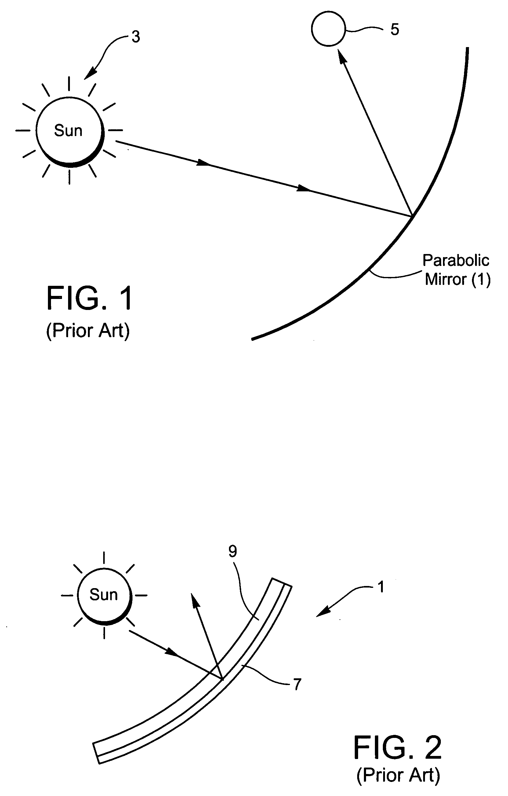
[0005]FIG. 2 is a cross sectional view of a typical mirror used in conventional solar collector systems. The mirror of FIG. 2 includes a reflective coating 7 supported by a single bent glass substrate 9, where the glass substrate 9 is on the light incident side of the reflective coating 7 (i.e., the incident light from the sun must pass through the glass before reaching the reflective coating). This type of mirror is a second or back surface mirror. Incoming light passes through the single glass substrate 9 before being reflected by the coating 7; the glass substrate 9 is typically from about 4-5 mm thick. Thus, reflected light passes through the glass substrate twice in back surface mirrors; once before being reflected and again after being reflected on its way to a viewer. Second or back surface mirrors, as shown in FIG. 2, are used so that the glass 9 can protect the reflective coating 7 from the elements in the external or ambient atmosphere in which the mirror is located (e.g., from rain, scratching, acid rain, wind-blown particles, and so forth).

Problems solved by technology

Unfortunately, the aforesaid process of manufacturing reflectors is problematic for at least the following reasons.
Second, during the manufacturing process, it is necessary to mirror-coat a 4-5 mm thick pre-bent glass sheet (a 4-5 mm thick pre-bent glass sheet will not sag flat during the mirror-coating process), and applying such coatings to bent glass is difficult at best and often leads to reduced reflective / mirror quality.

Method used


Image

  • Parabolic trough or dish reflector for use in concentrating solar power apparatus and method of making same
  • Parabolic trough or dish reflector for use in concentrating solar power apparatus and method of making same
  • Parabolic trough or dish reflector for use in concentrating solar power apparatus and method of making same

Examples


Embodiment Construction

[0036]Referring now more particularly to the accompanying drawings in which like reference numerals indicate like parts throughout the several views.

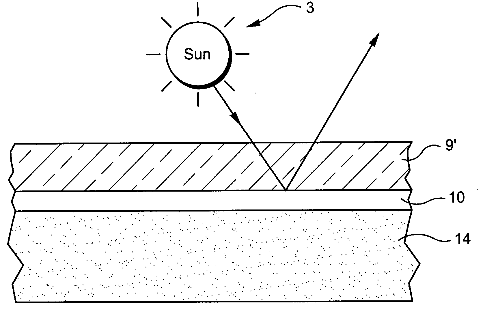
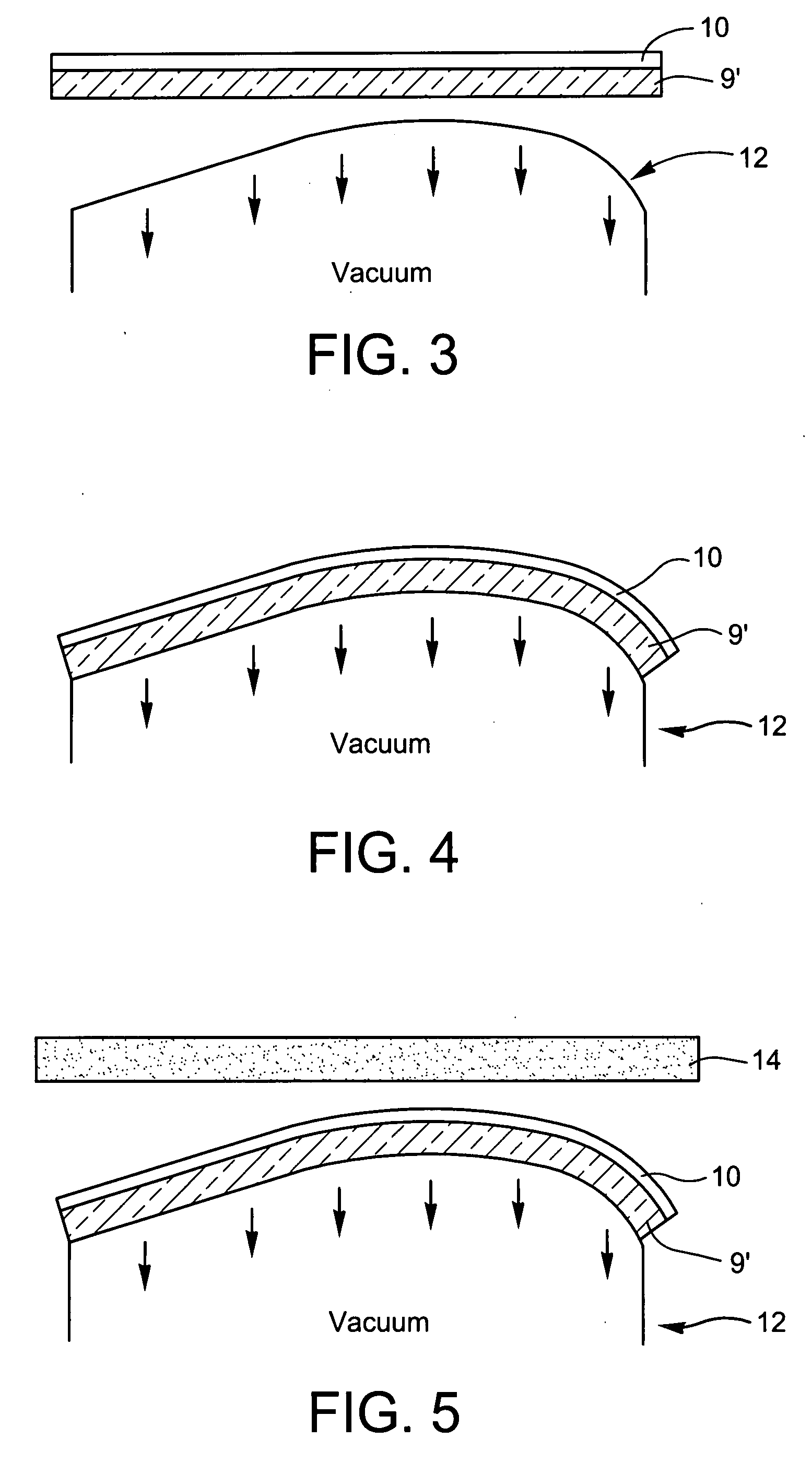
[0037]In certain example embodiments of this invention, a parabolic trough or dish reflector / mirror laminate for use in a concentrating solar power apparatus is made by: (a) forming a reflective coating on a thin substantially flat glass substrate (the thin glass substrate may or may not be pre-bent prior to the coating being applied thereto; if the thin glass substrate is pre-bent prior to application of the coating thereon then its thin nature and large size / weight will permit the glass to sag so as to be flat or substantially flat in the coating apparatus when the coating is applied thereto, such that the coating is still applied to a flat or substantially flat glass substrate even though it may have been pre-bent), (b) optionally, if the thin glass substrate in (a) was not pre-bent, cold-bending the thin glass substrate with the ref...


PUM

PropertyMeasurementUnit
thicknessaaaaaaaaaa
thicknessaaaaaaaaaa
solar reflectanceaaaaaaaaaa

Abstract

A reflector (e.g., mirror) for use in a solar collector or the like is provided. In certain example embodiments of this invention, a reflector is made by (a) forming a reflective coating on a thin substantially flat glass substrate (the thin glass substrate may or may not be pre-bent prior to the coating being applied thereto), (b) optionally, if the glass substrate in (a) was not prebent, then cold-bending the glass substrate with the reflective coating thereon; and (c) applying a plate or frame member to the thin bent glass substrate with the coating thereon from (a) and / or (b), the plate or frame member (which may be another thicker pre-bent glass sheet, for example) for maintaining the thin glass substrate and coating thereon in a desired bent orientation in a final product which may be used as parabolic trough or dish type reflector in a concentrating solar power apparatus or the like.

Description

[0001]This application is a continuation-in-part (CIP) of each of U.S. Ser. Nos. 11 / 416,388, filed May 3, 2006, Ser. No. 11 / 387,045, filed Mar. 23, 2006, and Ser. No. 11 / 452,418, filed Jun. 14, 2006, the disclosures of which are hereby incorporated herein by reference.[0002]Certain example embodiments of this invention are related to a reflector (e.g., mirror) for use in a solar collector or the like.BACKGROUND AND SUMMARY OF EXAMPLE EMBODIMENTS OF THE INVENTION[0003]Solar collectors are known in the art. Example solar collectors are disclosed in U.S. Pat. Nos. 5,347,402, 4,056,313, 4,117,682, 4,608,964, 4,059,094, 4,161,942, 5,275,149, 5,195,503 and 4,237,864, the disclosures of which are hereby incorporated herein by reference. Solar collectors include at least one mirror (e.g., parabolic or other type of mirror) that reflects incident light (e.g., sunlight) to a focal location such as a focal point. In certain example instances, a solar collector includes one or more mirrors that...

Claims


Application Information

Patent Timeline
Patent Type & Authority Applications(United States)
IPC IPC(8): G02B1/10F24S23/70F24S23/71F24S23/72F24S23/74
CPCF24J2/1057F24J2/12G02B5/10Y02E10/42B32B17/10036B32B17/10082B32B17/1022B32B17/10302B32B17/10761B32B17/10889B32B17/10091F24S23/71F24S23/74F24S23/82Y02E10/40
Inventor O'CONNOR, KEVINWANG, YEI-PING (MIMI) H.RECKER, DUANEVANDAL, ROBERT A.HADFIELD, SHANESOL, JEAN-MARCBRECHT, GREG
Owner GUARDIAN EURO S A R L
Learn More