
Method and apparatus for optimizing a train trip using signal information

a signal information and train technology, applied in adaptive control, navigation instruments, instruments, etc., can solve the problem that the operator cannot generally operate the locomotive to minimize fuel consumption

Active Publication Date: 2007-09-20
GE GLOBAL SOURCING LLC
View PDF80 Cites 143 Cited by
  • Summary
  • Abstract
  • Description
  • Claims
  • Application Information

AI Technical Summary

Benefits of technology

The present invention is a system for operating a railway network using a first railway vehicle during a trip along track segments. The system includes a first element for determining travel parameters of the first vehicle, a second element for determining travel parameters of a second vehicle relative to the track segments, and a processor for receiving information from the first and second elements and for determining a relationship between occupation of a track segment by the second vehicle and later occupation of the same track segment by the first vehicle. An algorithm is executed within the processor to create a trip plan that determines a speed trajectory for the first vehicle, which is responsive to the relationship and operational criteria for the first vehicle. The technical effect of this invention is to optimize the performance of the first vehicle during the trip along the track segments by considering the travel parameters of the second vehicle and other factors that may affect the vehicle's performance.

Problems solved by technology

However, even with sufficient knowledge and experience to assure safe operation, the operator generally cannot operate the locomotive to minimize fuel consumption (or other operating characteristics, e.g., emissions) during a trip.

Method used


Image

  • Method and apparatus for optimizing a train trip using signal information
  • Method and apparatus for optimizing a train trip using signal information
  • Method and apparatus for optimizing a train trip using signal information

Examples


Embodiment Construction

[0020]Reference will now be made in detail to the embodiments consistent with the aspects of the invention, examples of which are illustrated in the accompanying drawings. Wherever possible, the same reference numerals used throughout the drawings refer to the same or like parts.

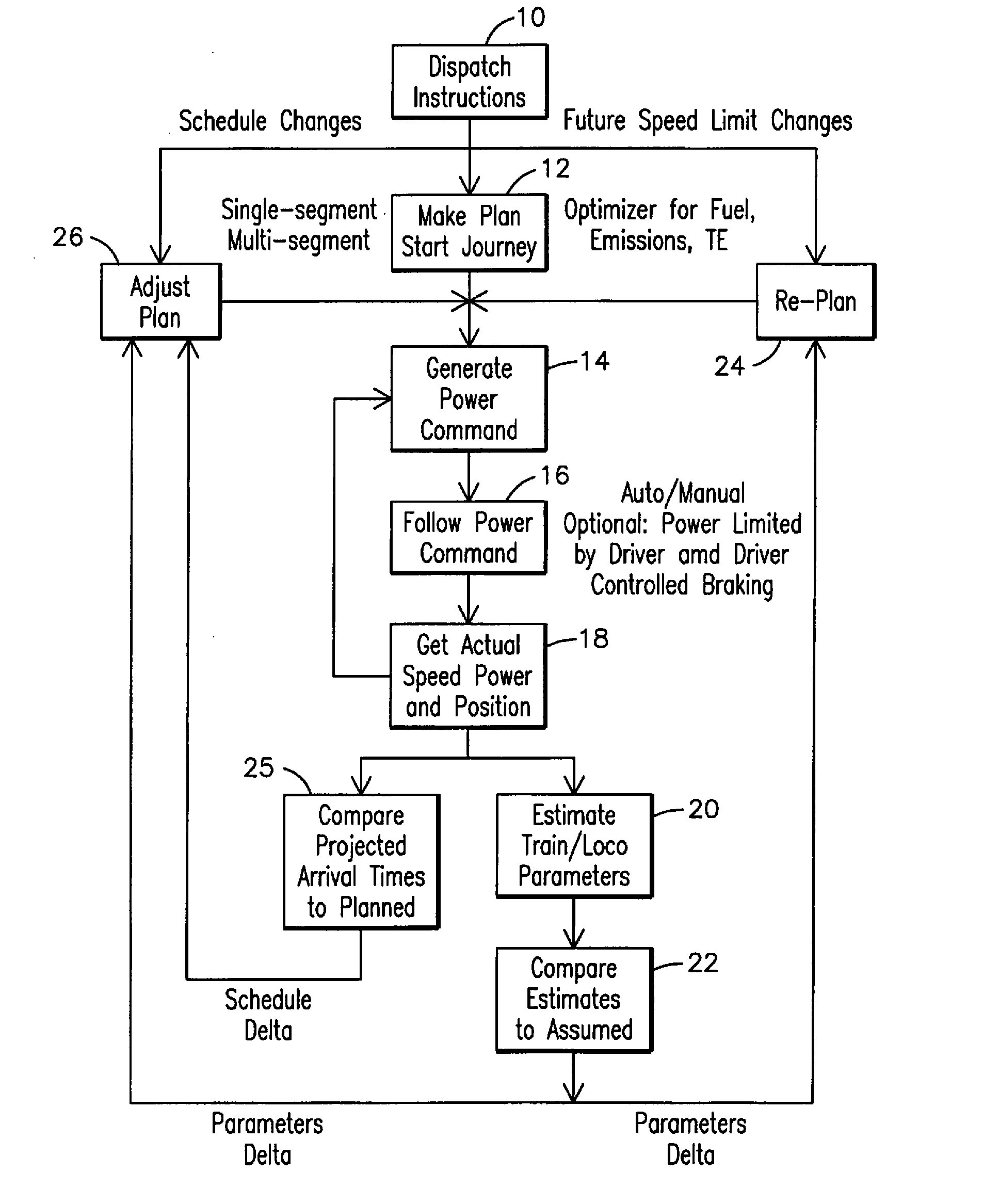
[0021]The embodiments of the present invention attempt overcome certain disadvantages in the art by providing a system, method, and computer implemented method for determining and implementing a driving strategy of a train including a locomotive consist and a plurality of railcars, by monitoring and controlling (either directly or through suggested operator actions) a train's operations to improve certain objective operating parameters while satisfying schedule and speed constraints. The present inventions are also applicable to a train including a plurality of locomotive consists spaced apart from the lead locomotive consist and controllable by the train operator (referred to as a distributed power train).

[...


PUM


Abstract

One embodiment of the invention includes a system for operating a railway network comprising a first railway vehicle (400) during a trip along track segments (401 / 412 / 420). The system comprises a first element (65) for determining travel parameters of the first railway vehicle (400), a second element (65) for determining travel parameters of a second railway vehicle (418) relative to the track segments to be traversed by the first vehicle during the trip, a processor (62) for receiving information from the first (65) and the second (65) elements and for determining a relationship between occupation of a track segment (401 / 412 / 420) by the second vehicle (418) and later occupation of the same track segment by the first vehicle (400) and an algorithm embodied within the processor (62) having access to the information to create a trip plan that determines a speed trajectory for the first vehicle (400), wherein the speed trajectory is responsive to the relationship and further in accordance with one or more operational criteria for the first vehicle (400).

Description

CROSS-REFERENCE TO RELATED APPLICATIONS[0001]This application is a continuation-in-part application claiming the benefit of U.S. patent application entitled Trip Optimization System and Method for a Train, filed on Mar. 20, 2006 and assigned application Ser. No. 11 / 385,354, which is hereby incorporated by reference.FIELD OF THE INVENTION[0002]The embodiments of the invention relate to optimizing train operations, and more particularly to using track and switch signals in conjunction with monitoring and controlling train operations to improve efficiency while satisfying schedule constraints.BACKGROUND OF THE INVENTION[0003]A locomotive is a complex system with numerous subsystems, each subsystem interdependent on other subsystems. An operator aboard a locomotive applies tractive and braking effort to control the speed of the locomotive and its load of railcars to assure safe and timely arrival at the desired destination. Speed control must also be exercised to maintain in-train force...

Claims


Application Information

Patent Timeline
Patent Type & Authority Applications(United States)
IPC IPC(8): G06F17/00
CPCB61L3/006B61L25/021B61L25/025B61C17/12B61L27/0027B61L2205/04G05B13/021B61L25/026B61L27/16B61L15/0058
Inventor KUMAR, AJITH KUTTANNAIRDAUM, WOLFGANGOTSUBO, TOMHERSHEY, JOHN ERIKHESS, GERALD JAMES
Owner GE GLOBAL SOURCING LLC
Learn More