String lamp assembly

a lamp assembly and string technology, applied in the direction of electrical equipment, contact members penetrating/cutting insulation/cable strands, coupling device connections, etc., can solve the problems of increasing the volume of the lamp holder, inconvenience in lamp assembly, and reducing the lifetime and working efficiency of the lamp assembly

Inactive Publication Date: 2007-09-20
TSAI CHIN SUNG
View PDF2 Cites 4 Cited by
  • Summary
  • Abstract
  • Description
  • Claims
  • Application Information

AI Technical Summary

Benefits of technology

[0005] In accordance with the present invention, there is provided a lamp assembly, comprising two juxtaposed electric cords, and a plurality of lamps each mounted on and electrically connected to the electric cords. Each of the lamps includes a lamp holder mounted on the electric cords, and a lamp cover mounted on the lamp holder and rested on the electric cords to clamp the electric cords between the lamp cover and the lamp holder. The lamp cover has an inside formed with two receiving grooves to receive distal ends of the electric cords to prevent the distal ends of the electric cords from being exposed outwardly from the lamp holder and the lamp cover.

Problems solved by technology

However, the distal ends of the electric cords 70 are protruded from the lamp holder 72 and the lamp cover 74 of the last lamp, so that it is necessary seal and hide the distal ends of the electric cords 70 in the lamp holder 72, thereby increasing the volume of the lamp holder 72, and thereby causing inconvenience in assembly of the lamps.
In addition, each of the lamps cannot provide water draining and air ventilating effects, thereby decreasing the lifetime and working efficiency of the lamp assembly.

Method used


Image

  • String lamp assembly
  • String lamp assembly
  • String lamp assembly

Examples


Embodiment Construction

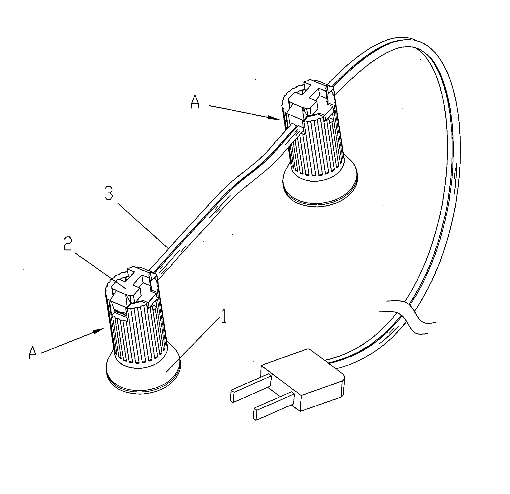
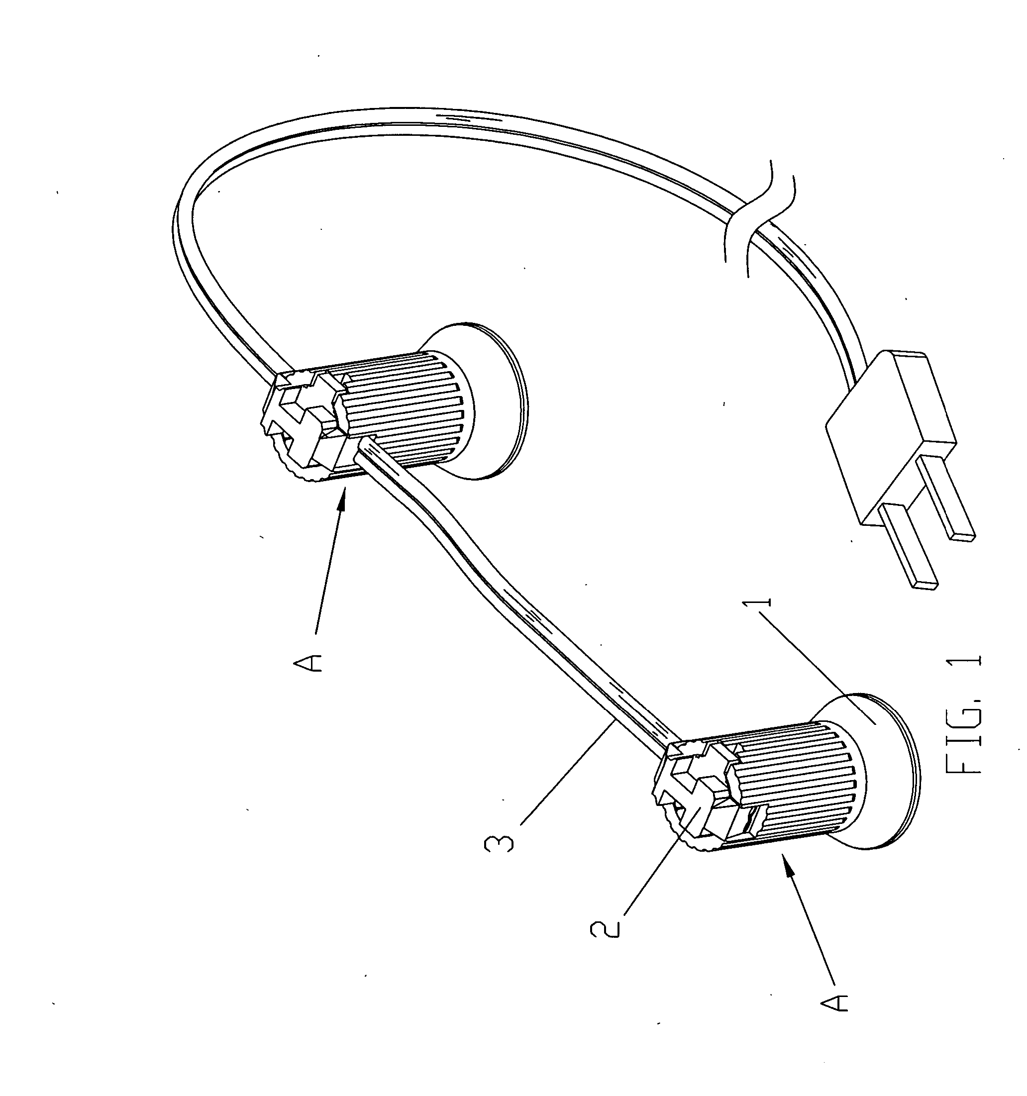
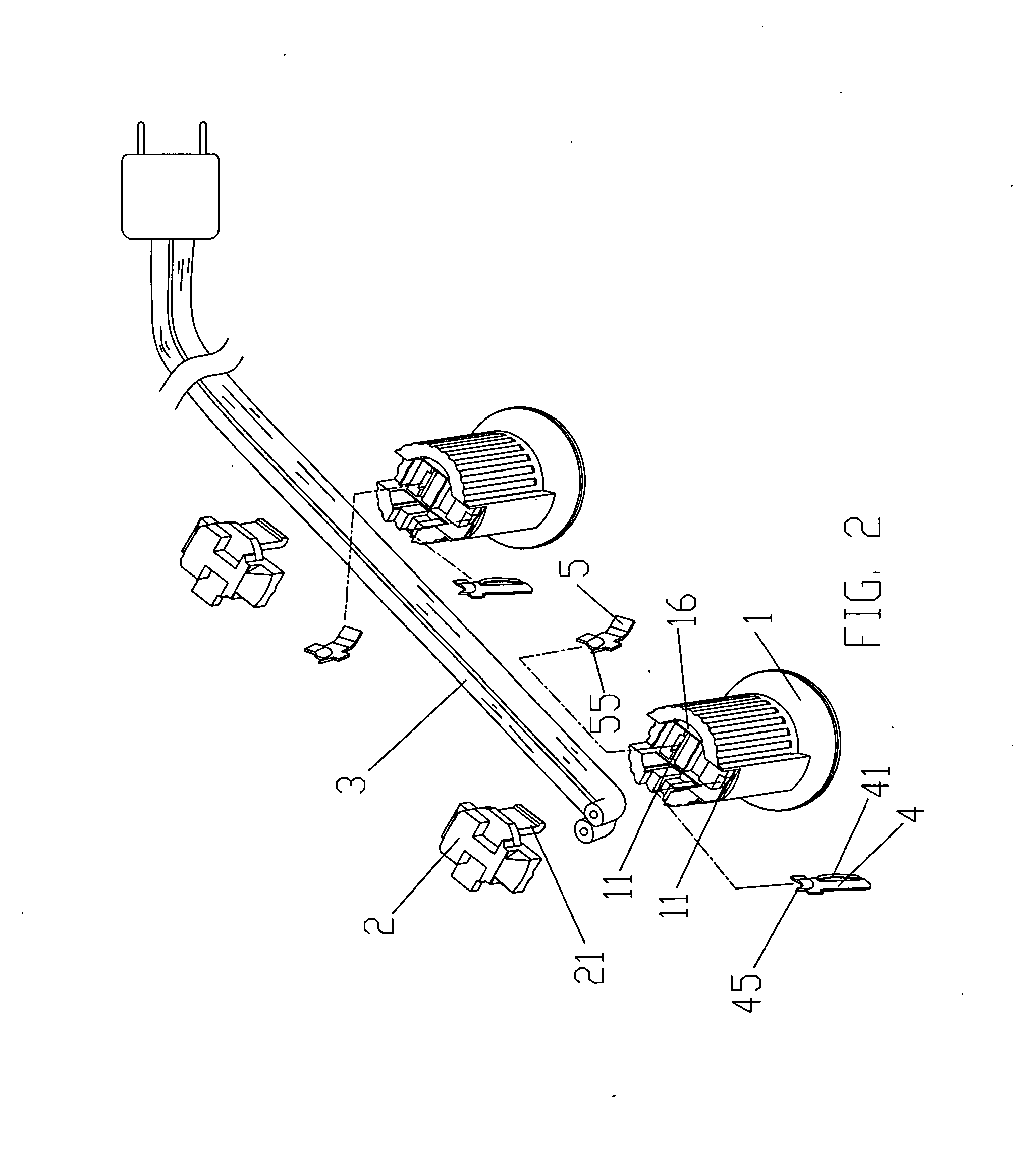
[0023] Referring to the drawings and initially to FIGS. 1-5, a lamp assembly in accordance with the preferred embodiment of the present invention comprises two juxtaposed electric cords 3, and a plurality of lamps “A” each mounted on and electrically connected to the electric cords 3.

[0024] Each of the lamps“A” includes a lamp holder 1 mounted on the electric cords 3, a first conducting plate 4 mounted in the lamp holder 1 and electrically connected to the respective electric cord 3, a second conducting plate 5 mounted in the lamp holder 1 and electrically connected to the respective electric cord 3, an electric bulb 6 mounted on the lamp holder 1 and electrically connected to the first conducting plate 4 and the second conducting plate 5, and a lamp cover 2 mounted on the lamp holder 1 and rested on the electric cords 3 to clamp the electric cords 3 between the lamp cover 2 and the lamp holder 1.

[0025] The lamp holder 1 is a cylindrical body and has two slots 11 to allow insertio...


PUM


Abstract

A lamp assembly includes two juxtaposed electric cords, and a plurality of lamps each mounted on the electric cords. Each of the lamps includes a lamp holder, and a lamp cover. The lamp cover has an inside formed with two receiving grooves. Thus, the distal ends of the electric cords are received in the receiving grooves of the lamp cover to prevent the distal ends of the electric cords from being exposed outwardly. In addition, the lamp cover has a periphery formed with a plurality of flattened edges to define a plurality of gaps between the lamp cover and the lamp holder to provide water draining and air ventilating effects.

Description

BACKGROUND OF THE INVENTION [0001] 1. Field of the Invention The present invention relates to a lamp assembly and, more particularly, to a string lamp assembly having a string of lamps. [0002] 2. Description of the Related Art [0003] A conventional string lamp assembly in accordance with the prior art shown in FIG. 8 comprises two juxtaposed electric cords 70, and a plurality of lamps (only one lamp is shown) each mounted on and electrically connected to the electric cords 70. Each of the lamps includes a lamp holder 72 mounted on the electric cords 70, two conducting plates (not shown) each mounted in the lamp holder 72 and each electrically connected to the respective electric cord 70, an electric bulb (not shown) mounted on the lamp holder 72 and electrically connected to the two conducting plates, and a lamp cover 74 mounted on the lamp holder 72 and rested on the electric cords 70 to clamp the electric cords 70 between the lamp cover 74 and the lamp holder 72. [0004] However, t...

Claims


Application Information

Patent Timeline
Patent Type & Authority Applications(United States)
IPC IPC(8): H01R4/24
CPCH01R4/2404H01R13/506H01R33/22H01R25/145H01R25/003H01R4/2406
Inventor TSAI, CHIN-SUNG
Owner TSAI CHIN SUNG
Why Eureka
Try Eureka