Translucent dust cap for fiber optic adapter

Active Publication Date: 2007-09-20
CORNING OPTICAL COMM LLC
View PDF29 Cites 70 Cited by
  • Summary
  • Abstract
  • Description
  • Claims
  • Application Information

AI Technical Summary

Benefits of technology

[0008] In one aspect, the present invention is directed to a translucent adapter dust cap that allows for the identification of visible light emanating from a fiber optic connector while the connector is loaded into an adapter, without removing the dust cap. In an exemplary application, the adapter may be disposed within a patch panel such that a connector is pre-installed into the back side of the adapter, and the translucent adapter dust cap is loaded into the front side of the adapter until an interconnection with a fiber optic connector of another fiber optic jumper is attempted. The translucent adapter dust cap is preferably designed such that it mates in a manner similar to a connector that would be loaded into the front side of the adapter, thus providing the best seal between the dust cap and the adapter. The dust cap is preferably made from a translucent plastic material and preferably includes a spot of paint or other opaque or absorbent material about the optical axis, thus preventing eye damage that may be caused by the visible or invisible light source. The internal geometry of the dust cap may function to reflect or diffuse a light source of sufficient power, such as that from a visual fault locator (VFL). Alternatively, a material may be chosen that absorbs damaging wavelengths of light.
[0009] In another aspect, the present invention is directed to a translucent adapter dust cap that not only addresses the identification shortcomings of other conventional dust caps, but also functions in an improved manner to further reduce the opportunity for contaminants and other debris to be deposited upon the polished front face of the ferrule. This is accomplished by allowing the dust cap to remain loaded into the adapter during identification and until the front side of the adapter is needed. Thus, the translucent adapter dust cap may be loaded into the adapter the entire time the connector is loaded into the back side of the adapter, until the front side of the adapter is needed for interconnection with another connector, reducing the time and opportunity for debris to enter the adapter. The translucent adapter dust cap is preferably constructed such that at least the closed end is translucent in order to permit the optical identification. In various embodiments, there may be a protrusion of the dust cap into the bore of the adapter towards the connector ferrule while providing a clearance for the connector ferrule. The dust cap preferably seals with the adapter when an interior surface of the dust cap substantially surrounds an internal feature of the adapter, thus providing a seal and preventing contaminants from reaching the polished end face of the connector ferrule.

Problems solved by technology

In either case, the opportunity then exists for eye damage from the invisible light if a connector with infrared transmission laser power is viewed accidentally.
Further, removing the connector from its respective adapter or removing the dust cap from the connector may also allow dust and contaminants to reach the polished end face of the ferrule, resulting in damage or signal degradation.
Other conventional dust caps have been developed to allow for the identification of visible light without the removal of the dust cap from the ferrule, but do not allow for the identification of the visible light through the dust cap once the connector is loaded into an adapter, due to the fact that the dust cap must be removed from the ferrule prior to inserting the connector into the adapter.
While these examples of conventional dust caps do prevent dust contamination and allow visible light identification in certain applications, by design they are not able to provide both protection against dust contamination and the ability to identify visible light emanating from the connector while the connector is loaded into an adapter.

Method used


Image

  • Translucent dust cap for fiber optic adapter
  • Translucent dust cap for fiber optic adapter
  • Translucent dust cap for fiber optic adapter

Examples


Embodiment Construction

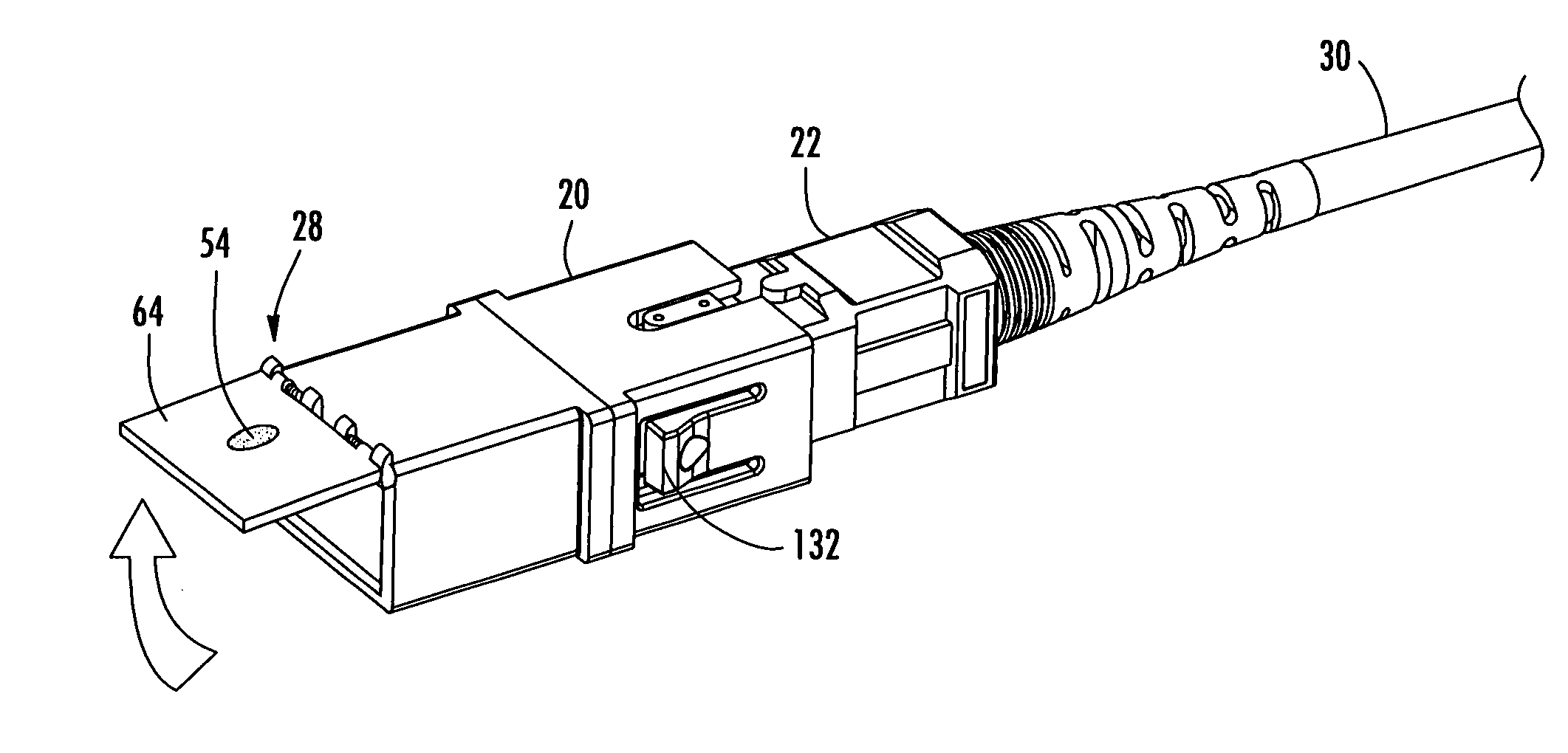
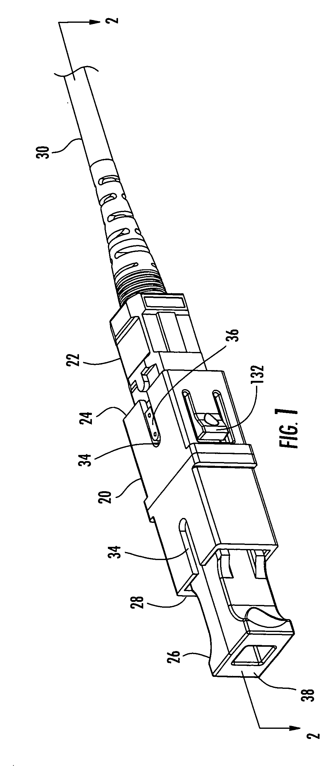
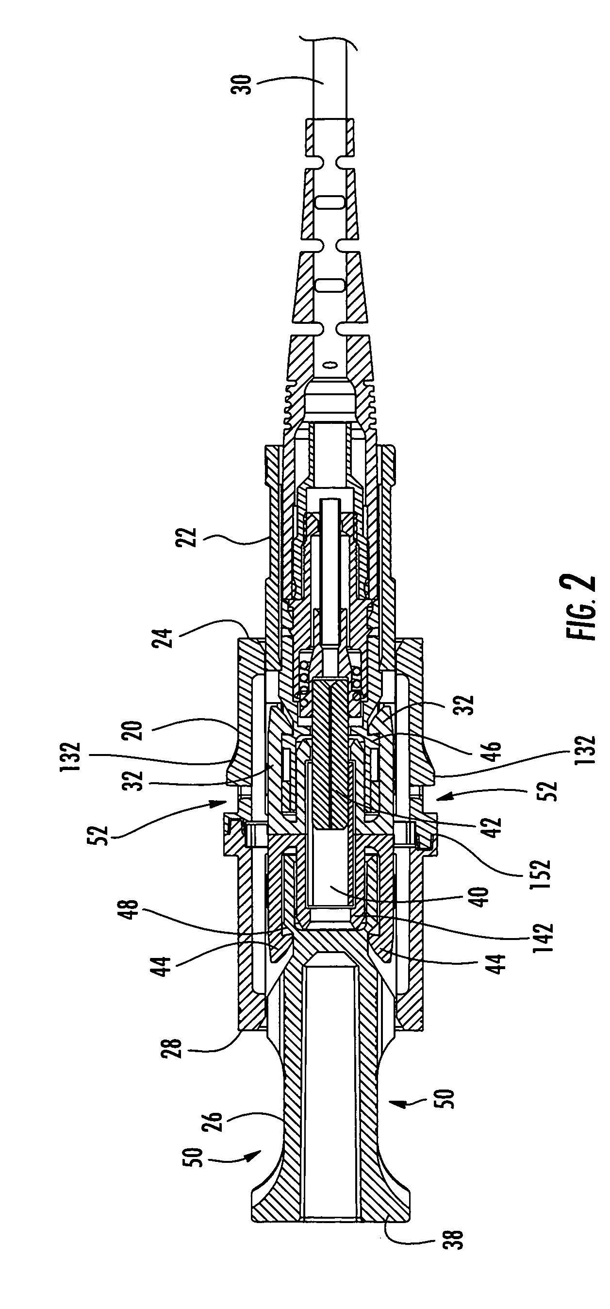
[0021] Reference will now be made in greater detail to various exemplary embodiments of the invention, preferred embodiments of which are illustrated in the accompanying drawings. Whenever possible, the same reference numerals will be used throughout the drawings to refer to the same or similar parts. Specific embodiments of translucent adapter dust caps operable for allowing the viewing of light emanating from a fiber optic connector while the connector is loaded into the adapter are shown throughout the figures. It should be understood, however, that alternative translucent adapter dust cap designs may vary in order to accommodate other fiber optic connector adapters, including, but not limited to, single fiber and multi-fiber versions of SC, ST, LC, FC MTP and MU connectors, among others. Alternative translucent adapter dust cap designs may also vary while still proving protection against dust contamination and blocking light transmitted along the optical axis.

[0022] Referring n...


PUM


Abstract

A translucent dust cap for a fiber optic adapter allows the viewing of visible light emanating from a fiber optic connector coupled to the adapter, without removing the dust cap. A translucent dust cap for a fiber optic adapter that serves to diffuse a visible light source of sufficient power, such as that from a VFL, and lights up to aid in connector identification. A translucent dust cap for a fiber optic adapter that serves to attenuate infrared optical transmission power to prevent eye damage.

Description

BACKGROUND OF THE INVENTION [0001] 1. Field of the Invention [0002] The present invention relates generally to dust caps that are mounted upon fiber optic connector adapters and, more particularly, to translucent fiber optic adapter dust caps that allow the identification of light emanating from a fiber optic connector while the connector is capped or loaded into an adapter, while also providing protection against eye damage and dust contamination. [0003] 2. Technical Background [0004] Fiber optic applications using optical connectors and adapters frequently include requirements for the identification of specific optical fibers during installation, interconnection and maintenance testing. Examples of such applications include local area networks, industrial networks and structured cabling systems, among others. Within these systems, connections between optical fibers are typically accomplished through the use of one or more patch panels. A patch panel typically includes a large numb...

Claims


Application Information

Patent Timeline
IPC IPC(8): G02B6/36
CPCG02B6/3849
Inventor JONG, MICHAEL DEHARVEY, GERRY J.
Owner CORNING OPTICAL COMM LLC
Why Eureka
Try Eureka