
Tray for component packaging

Inactive Publication Date: 2007-09-20
FCI AMERICAS TECH INC (US)
View PDF7 Cites 23 Cited by
  • Summary
  • Abstract
  • Description
  • Claims
  • Application Information

AI Technical Summary

Benefits of technology

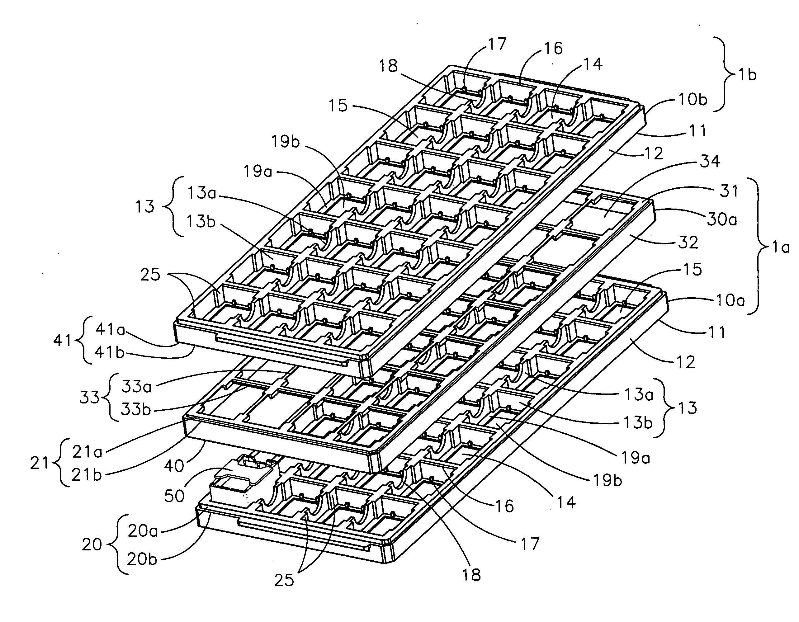
[0009] Constructing the packaging tray in multiple parts allows the packaging tray to be loaded in the placement equipment with or without the spacer tray, thereby accommodating varying lift travel of the placement equipment.
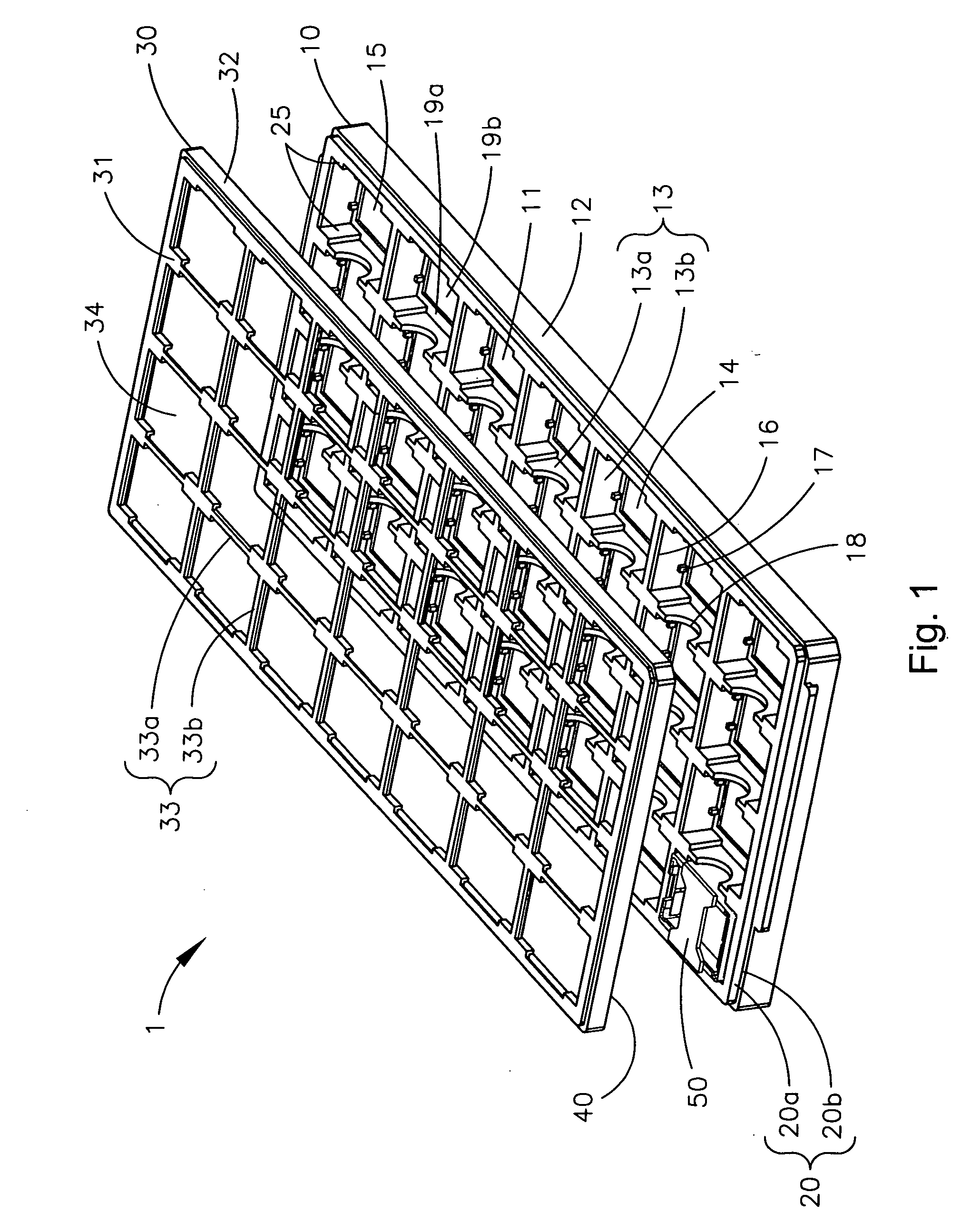
[0010] This design makes it possible for placement equipment with limited available lift travel to operate by having the tray constructed in multiple components. A base that holds the part and is design to allow a part to be lifted out of the based with the lift available on the placement equipment and a spacer tray that extends from the base up around the part to protect the part and to make it possible for the trays to be stacked on top of one another.
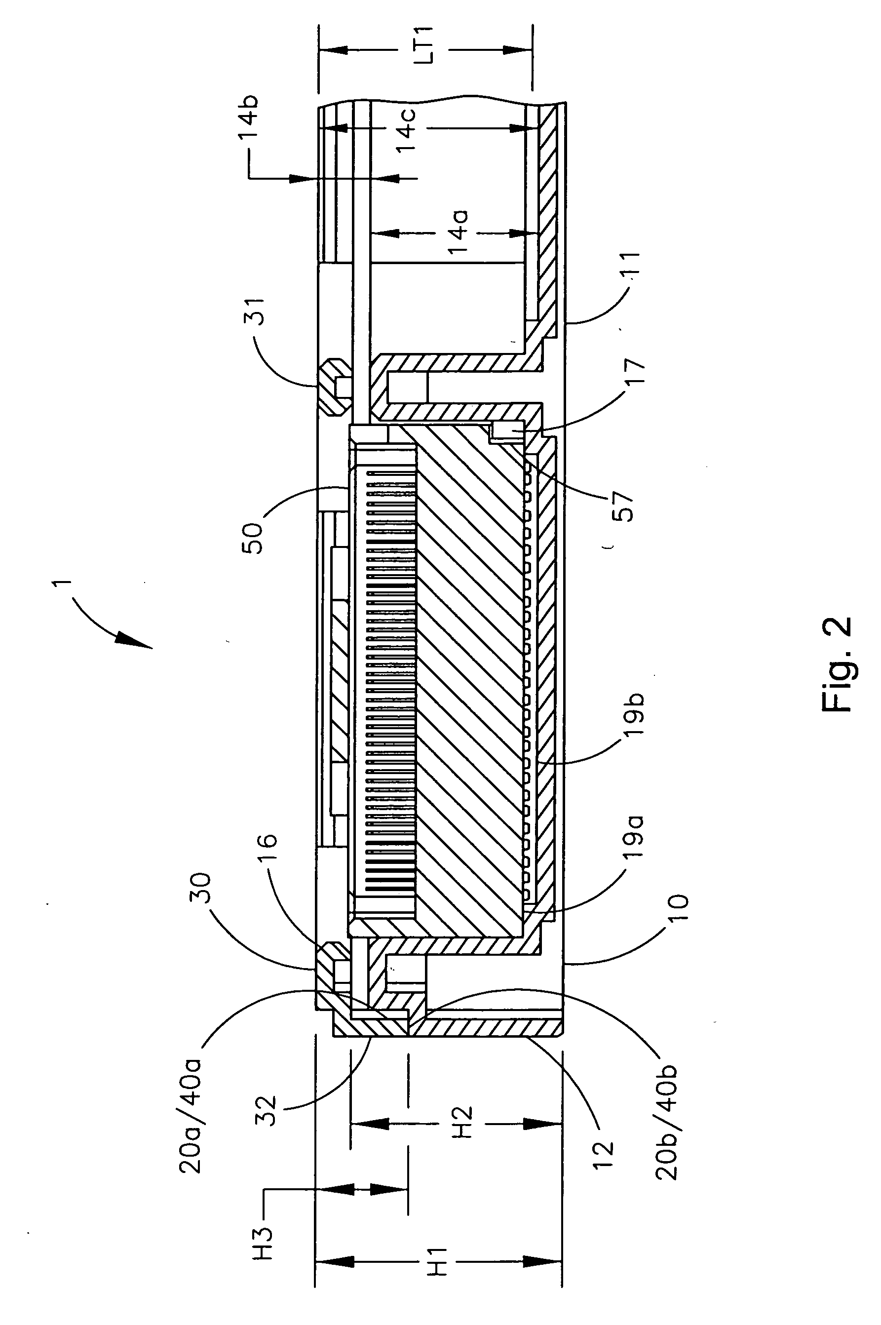
[0011] The component packaging tray preferably minimizes the vertical lift travel required to remove a component from the tray. The tray for component packaging addresses multiple pick and place equipment needs concerning the height of the product stored in each individual storage pocket. The tray for component packaging preferably fits a plurality of pick and place systems.
[0012] For equipment with limited lift travel the spacer tray can be removed and the tray can be introduced to the placement equipment. When the spacer tray is removed, the lift travel required to remove the component from the tray is reduced / minimized. Reduced lift travel helps improve placement time and efficiencies.

Problems solved by technology

There exists a problem as components get larger that some placement equipment have limitations on the amount of travel available to lift a component out of a tray.
In addition, problems exists in that certain automated handling equipment can not handle trays having different size pockets for holding components having varying heights due to limited available lift travel.
The integrated circuit storage trays disclosed in U.S. Pat. No. 5,103,976 and U.S. Pat. No. 5,335,771, however, do not address multiple pick and place equipment needs concerning the height of the product stored in each individual storage pocket.
The trays disclosed in U.S. Pat. No. 5,957,293 require a common tray design for all trays used in the industry by many manufacturers and do not address multiple pick and place equipment needs concerning the height of the product stored in each individual storage pocket.
This approach also fails to address the concerns relating to multiple pick and place requirements on height of parts found in all or most existing pick and place equipment.

Method used


Image

  • Tray for component packaging
  • Tray for component packaging
  • Tray for component packaging

Examples


Embodiment Construction

[0030] The present invention is directed to trays for component packaging. The packaging tray 1 may be constructed in multiple pieces to accommodate varying lift travel available to lift components 50 having different heights out of the packaging tray 1. This multiple part design makes it possible for handling and / or placement equipment 70 with limited available lift travel to operate by having a removable spacer tray 30 disposed over a base tray 10. The base tray 10 holds the component 50 and is designed and constructed to reduce and / or minimize the lift travel required to lift the component out of the base tray 10. The spacer tray 30 extends from the base tray 10 up and around the component 50 to protect the component 50 and to allow trays 1 to be stacked on top of one another.

[0031] This concept of a multi-piece packaging tray 1 applies to applications wherein lift travel available may be inadequate to lift the component from the tray 1. This concept of a multi-piece packaging t...


PUM


Abstract

A tray for component packaging that allows components having varying heights to be automatically removed from the tray. The packaging tray allows for all or most removal systems to function regardless of the component height. The packaging tray includes a base tray for holding a component and a removable spacer tray that extends upward from the base tray to cover and protect the component. During automatic removal of the component from the tray, the spacer tray may be removed to reduce and / or minimize the vertical lift travel required to remove the component from the tray. The spacer tray may be left in place during the removal process and is constructed to allow removal of the component. The spacer tray may provide a top surface that is substantially flush with the top of the component and may be left in place during the removal process for removal systems that require that the over sized (height) components be substantially flush with the top surface of the tray during removal from the tray.

Description

RELATED APPLICATION [0001] The subject matter disclosed herein is related to the subject matter disclosed in Provisional U.S. Patent Application having Ser. No. 60 / 782,777, filed Mar. 16, 2006, entitled “Tray For Component Packaging”; which is assigned to the assignee of the present application and hereby incorporated herein by reference in its entirety.FIELD OF THE INVENTION [0002] Generally, the invention relates to trays for component packaging. More particularly, the invention relates to a packaging tray constructed in multiple parts to accommodate varying lift travel available for removing components from the tray. This technology is particularly suited, but by no means limited, for holding surface mount components designed to be applied to a mounting surface. BACKGROUND OF THE INVENTION [0003] Surface mount components may be applied to printed circuit boards through automated equipment. This equipment is typically referred to as pick and placement equipment and may be fully au...

Claims


Application Information

Patent Timeline
IPC IPC(8): B65D85/00B65D1/34
CPCH01L21/67333
Inventor HOLLER, RONALD P.
Owner FCI AMERICAS TECH INC (US)
Learn More