
Remote control apparatus, remote control system and device-specific information display method

Active Publication Date: 2007-09-13
FUJIFILM CORP
View PDF24 Cites 38 Cited by
  • Summary
  • Abstract
  • Description
  • Claims
  • Application Information

AI Technical Summary

Benefits of technology

[0006]The present invention has been made in consideration of the above problem, and an object thereof is to suspend information display of certain devices in order to suppress disorderliness of a screen and enable remote control of devices to be easily performed.
[0008]Conventionally, since specific information was uniformly superimposed and displayed regardless of the states of devices, selection of a desired control device and control contents was impeded. However, since the present invention arranges displaying of information specific to the device to be suspended according to device state information, the risk of remote control being impeded by the specific information displayed in an indiscriminant and disordered manner may be reduced, and efficient remote control operations may be realized.
[0012]By suspending display of information specific to the device that is in a state in which control of original operations thereof have been restricted, information that is less likely required to be displayed for operations may be erased from the screen, thereby enabling control of original operations of other devices in an easier manner.
[0015]By arranging displaying of the information specific to the device to be suspended according to state information of the device, the present invention may reduce the risk of remote control being impeded by specific information displayed in an indiscriminant and disordered manner, and efficient remote control operations may be achieved.

Problems solved by technology

An increase in the number of displayed IDs of devices in sleep mode results in the display becoming more disordered, thereby impeding operations and causing image synthesis processing to become cumbersome.
Conventionally, since specific information was uniformly superimposed and displayed regardless of the states of devices, selection of a desired control device and control contents was impeded.

Method used


Image

  • Remote control apparatus, remote control system and device-specific information display method
  • Remote control apparatus, remote control system and device-specific information display method
  • Remote control apparatus, remote control system and device-specific information display method

Examples


Embodiment Construction

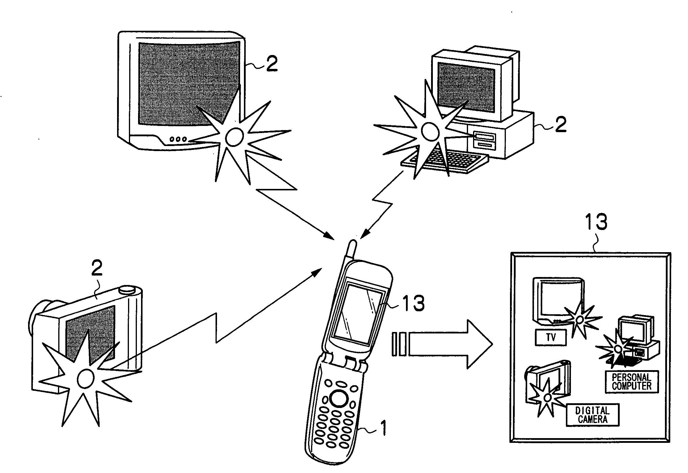
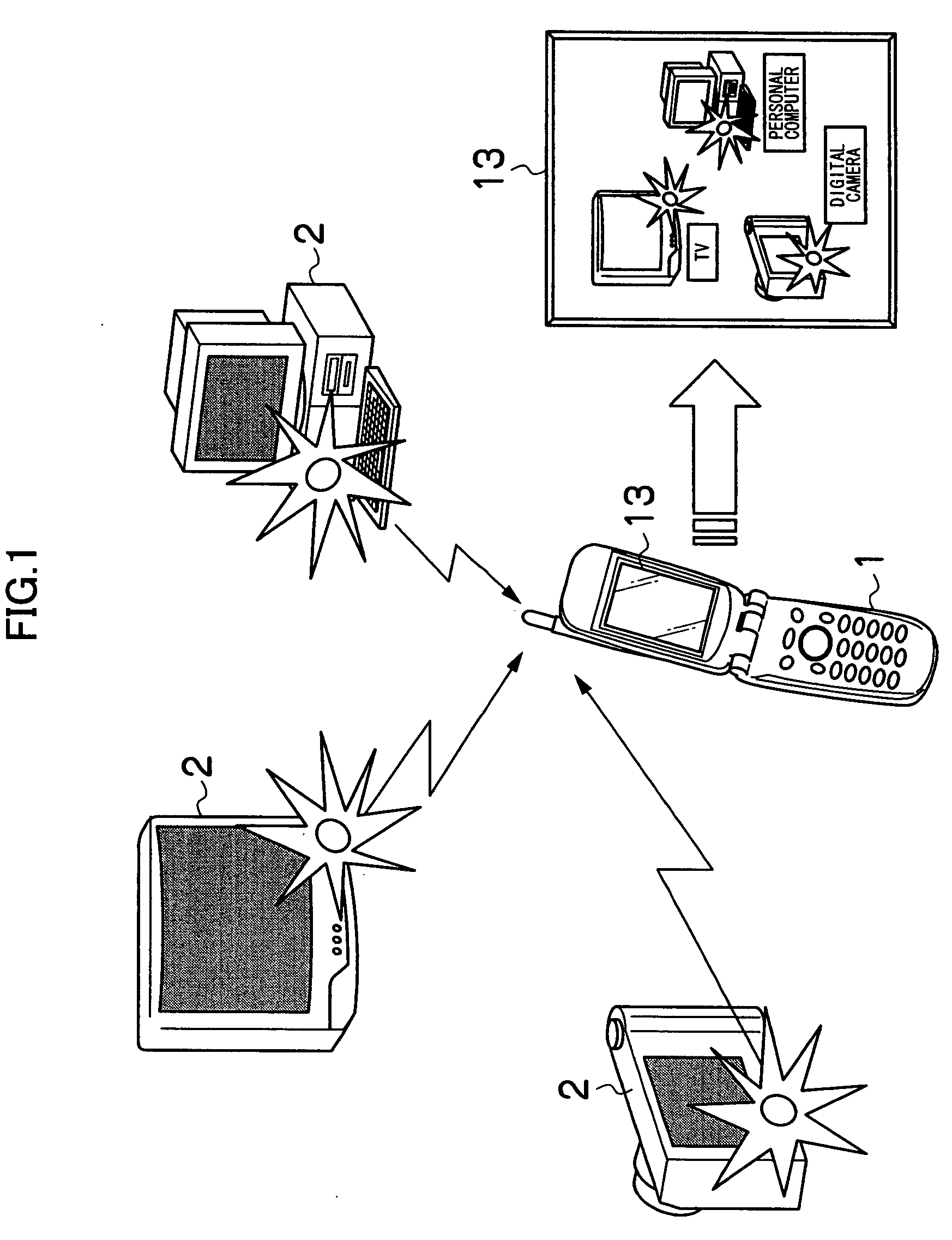
[0022]FIG. 1 is a schematic configuration diagram of a remote control system according to a preferred embodiment of the present invention. The system comprises a remote control apparatus 1, and other devices 2 which may be an AV device controlled by the remote control apparatus 1 such as a television, video, stereo, or a personal computer, a cooking appliance and the like. The remote control apparatus 1 connects to each of the devices 2 via an external network such as a mobile communication network or the Internet, or a local area network (LAN).

[0023]When all operations of a device 2 is remote-controllable (for instance, when the main power of the device 2 is turned on), the device 2 superimposes a low-frequency pilot signal for notifying its own information transmission position onto device-specific information that is information specific to the device (this information may be an identification number, an ID, a serial number, a manufacturer number, a model number, a model of the d...


PUM


Abstract

The present invention relates to a technique for acquiring information specific to a device via an imaging element and performing remote-control of a desired device based on the acquired information specific to the device, and an object thereof is to suspend information display of certain devices in order to suppress disorderliness of a screen and enable remote control of devices to be easily performed. By arranging displaying of the information specific to the device to be suspended according to device state information, the present invention can reduce the risk of remote control being impeded by specific information displayed in an indiscriminant and disordered manner, and efficient remote control operations may be achieved.

Description

BACKGROUND OF THE INVENTION[0001]1. Field of the Invention[0002]The present invention relates to a technique for acquiring device-specific information via an imaging element and performing remote-control of a desired device based on acquired device-specific information.[0003]2. Description of the Related Art[0004]In recent years, various techniques have been developed which enable control of a desired device among a plurality of devices using a single controller in an intuitive and readily understood manner. For instance, according to “Proposal of ‘OPTO-NAVI’ System, which is an information-appliance multi-purpose remote controller using a low power consumption ID-receiving CMOS image sensor having a function of reading a partial area at a high speed” (The Journal of the Institute of Image Information and Television Engineers Vol. 59, No. 12, pp. 1830-1840 (2005)), a custom image sensor mounted on a mobile phone is used to receive an ID from an information appliance while performing...

Claims


Application Information

Patent Timeline
IPC IPC(8): G06F12/14
CPCG08C17/02G08C23/04G08C2201/42H04N2201/0084H04N1/00127H04N1/00323G08C2201/93
Inventor OTA, MOTOARIMISAWA, TAKESHIMIYASHITA, TAKESHI
Owner FUJIFILM CORP
Learn More