
Automated disk clamping method for spinstand for testing magnetic heads and disks

Inactive Publication Date: 2007-09-13
GUZIK TECHN ENTERPRISES
View PDF4 Cites 2 Cited by
  • Summary
  • Abstract
  • Description
  • Claims
  • Application Information

AI Technical Summary

Benefits of technology

[0010] The present disclosure is directed to an apparatus and method which mitigates the aforementioned prior art limitations. According to one exemplary embodiment of the present disclosure, the apparatus comprises a base, rigidly atta

Problems solved by technology

These vibrations increase track misregistration.
In some cases, track misregistration reaches unacceptable levels at which spinstand operation becomes unreliable.
This creates two problems.

Method used


Image

  • Automated disk clamping method for spinstand for testing magnetic heads and disks
  • Automated disk clamping method for spinstand for testing magnetic heads and disks
  • Automated disk clamping method for spinstand for testing magnetic heads and disks

Examples


Embodiment Construction

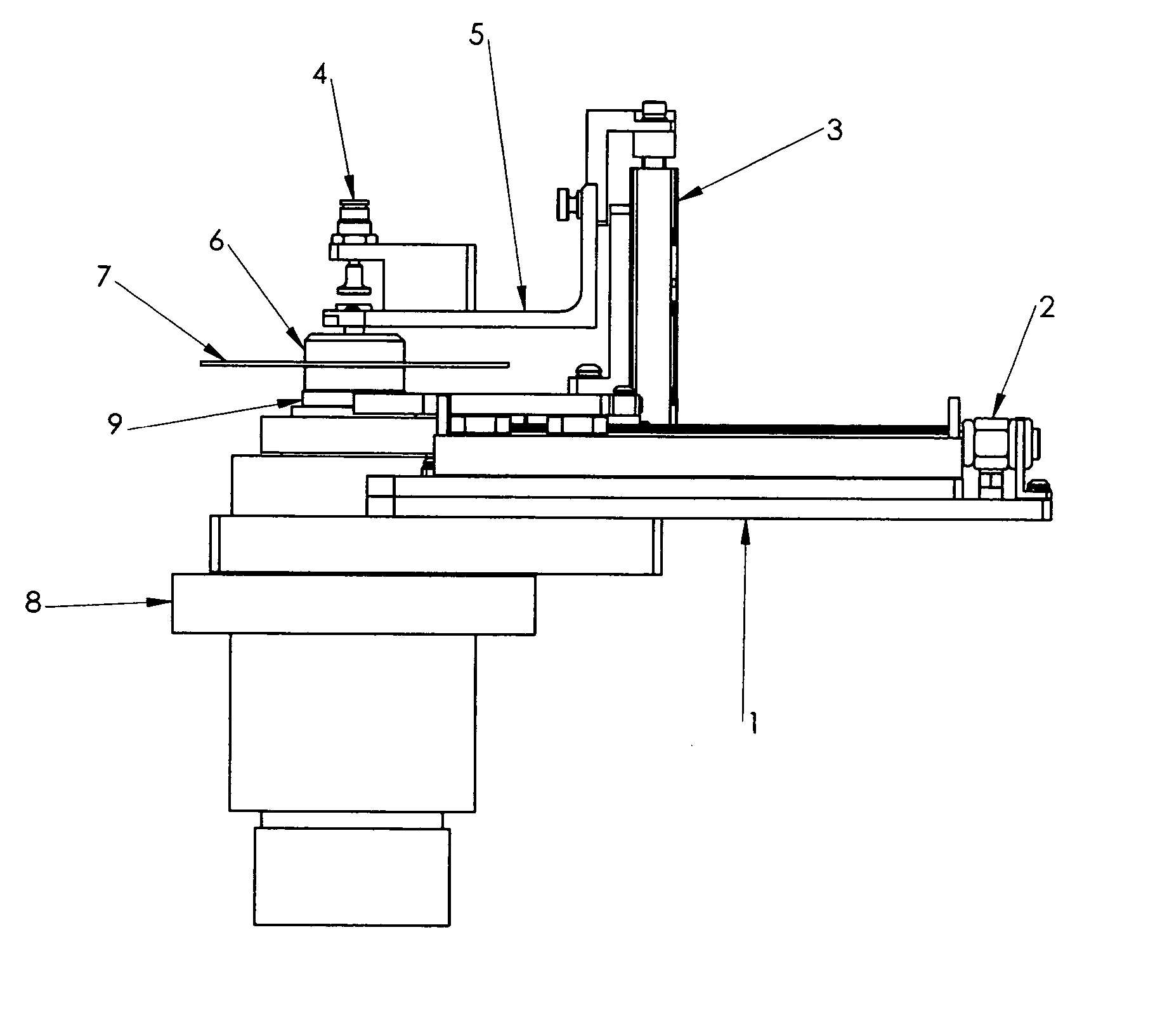
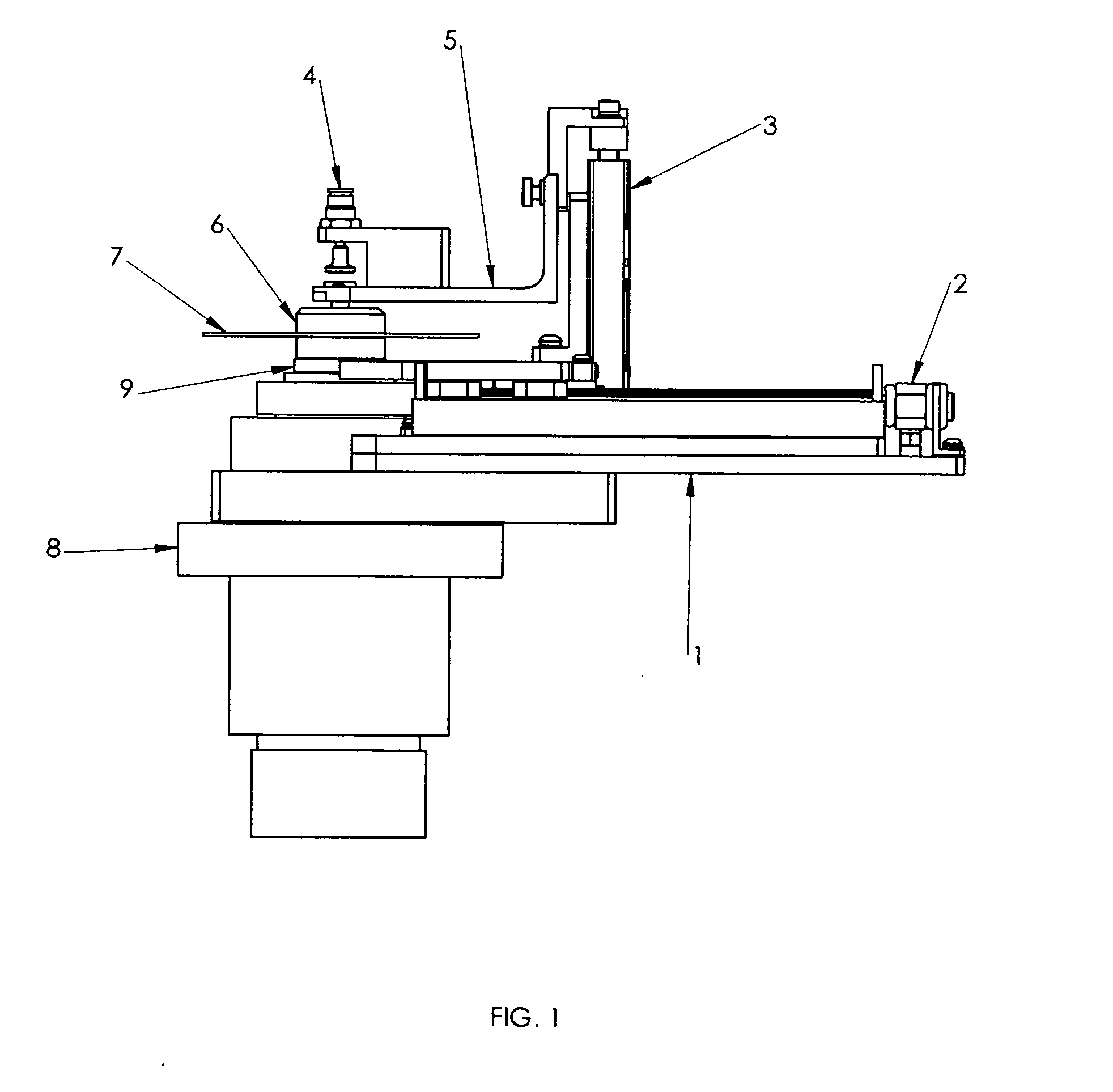
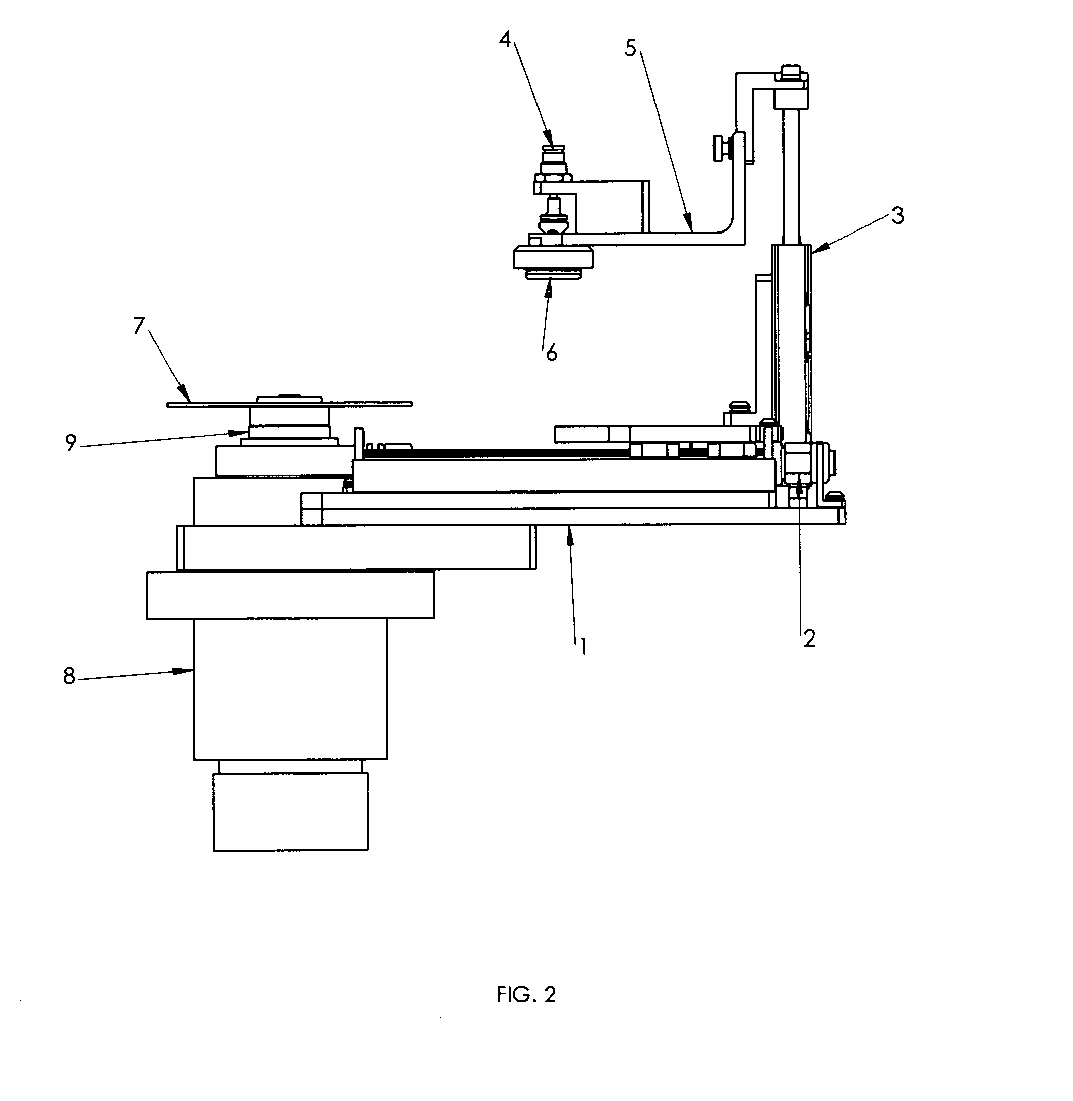
[0020] The present invention is an apparatus operable with a vacuum chuck assembly of the type shown FIG. 8, or a similar two piece clamp / chuck assembly, to automatically, preferably without user intervention, place a cap onto a magnetic disk supported on a base. With the cap so placed, the apparatus of the invention automatically, preferably without user intervention, automatically applies a clamp force to the cup and base to hold the magnetic disk in a desired position, for example on a spindle of a spinstand adapted to apply test signals and evaluate the magnetic disk and / or magnetic heads.

[0021] The apparatus of the invention in a preferred form includes a support on a base unit, for holding the base of a chuck assembly in place on a spinstand spindle, in a position to receive a magnetic disk-to-be tested or take-used-for test. A bracket is adapted with an end effector to selectively pick-up, hold and transport a cap for placement on the chuck base, securing the magnetic disk-t...


PUM


Abstract

A mechanism for placing and removing a vacuum clamping device for a magnetic disk on a spinstand, comprised of automated vertical and horizontal movement arranged such that a vacuum disk chuck, comprised of a base (9) and cap (6), can be used without operator interaction. Linear actuators provide the horizontal (2) and vertical (3) movement forces to accurately move a chuck cap (6) over a magnetic disk (7) that has been placed on a chuck base (9). The same actuators remove the cap and move it away from the disk to allow quick replacement of the disk. The interface between the mechanism and disk chuck cap is designed such that the cap is securely held during motion, and does not create particles.

Description

RELATED APPLICATION [0001] This application is related to U.S. Patent Application Ser. No. 60 / 759,536, (Attorney Docket No. GUZL-180PR), filed Jan. 17, 2006, entitled Automated Disk Clamping Method for Spinstand for Testing Magnetic Heads and Disks, and incorporated by reference herein.FIELD OF THE DISCLOSURE [0002] The present disclosure relates to spinstands and, in particular, to automatically securing disks mounted on and spun by a spindle of a spinstand with a vacuum chuck clamping device. BACKGROUND OF THE DISCLOSURE [0003] A magnetic head and disk tester is an instrument that is used for testing the characteristics of magnetic heads and disks, such as a signal-to-noise ratio, track profile, etc. The tester should simulate those motions of the head with respect to the disk and the same rotational speeds of the disks that occur in an actual hard disk drive during operation. Each tester consists of two components, i.e., a mechanical component, commonly referred to as a spinstand...

Claims


Application Information

Patent Timeline
IPC IPC(8): G01R33/12
CPCG11B5/4555G11B5/455
Inventor GUZIK, NAHUMRAY, FOREST
Owner GUZIK TECHN ENTERPRISES
Learn More