
Holographic arrays for multi-path imaging artifact reduction

a multi-path imaging and artifact technology, applied in the field of multi-path imaging artifact reduction, can solve the problems of reducing the resolution of the resulting image, not being well received by the public, and typically producing image artifacts, so as to achieve the effect of removing multi-path imaging artifacts

Active Publication Date: 2007-09-06
BATTELLE MEMORIAL INST
View PDF15 Cites 17 Cited by
  • Summary
  • Abstract
  • Description
  • Claims
  • Application Information

AI Technical Summary

Benefits of technology

The present invention provides a method to remove multi-path imaging artifacts in an imaging system using a transmitter and a receiver. The transmitter transmits an elliptical polarization signal, and the receiver receives the reflected signal. The reflected signal is then analyzed to identify those portions where the polarity of the characteristic has been reversed. The invention can use a fully polarimetric configuration or a more limited configuration. The method can be used with different types of polarization and can detect and identify the state of polarization, as well as the number of reflections. The technical effect of the invention is to improve the quality of images obtained from the reflected signals and to reduce the impact of multi-path imaging artifacts.

Problems solved by technology

These systems can be very effective, however, they are bulky and may not be well-received by the public due to their use of ionizing radiation (even though they operate at low x-ray levels).
The resolution of the resulting images is diffraction-limited, i.e. it is limited only by the wavelength of the system, aperture size, and range to the target and is not reduced by the reconstruction process.
All imaging systems proposed for personnel screening typically produce image artifacts, created by the detection of signals that have been reflected more than one time (multipath) by the item being imaged.
These artifacts are undesirable because they distract from the underlying item being imaged, such as concealed objects.

Method used


Image

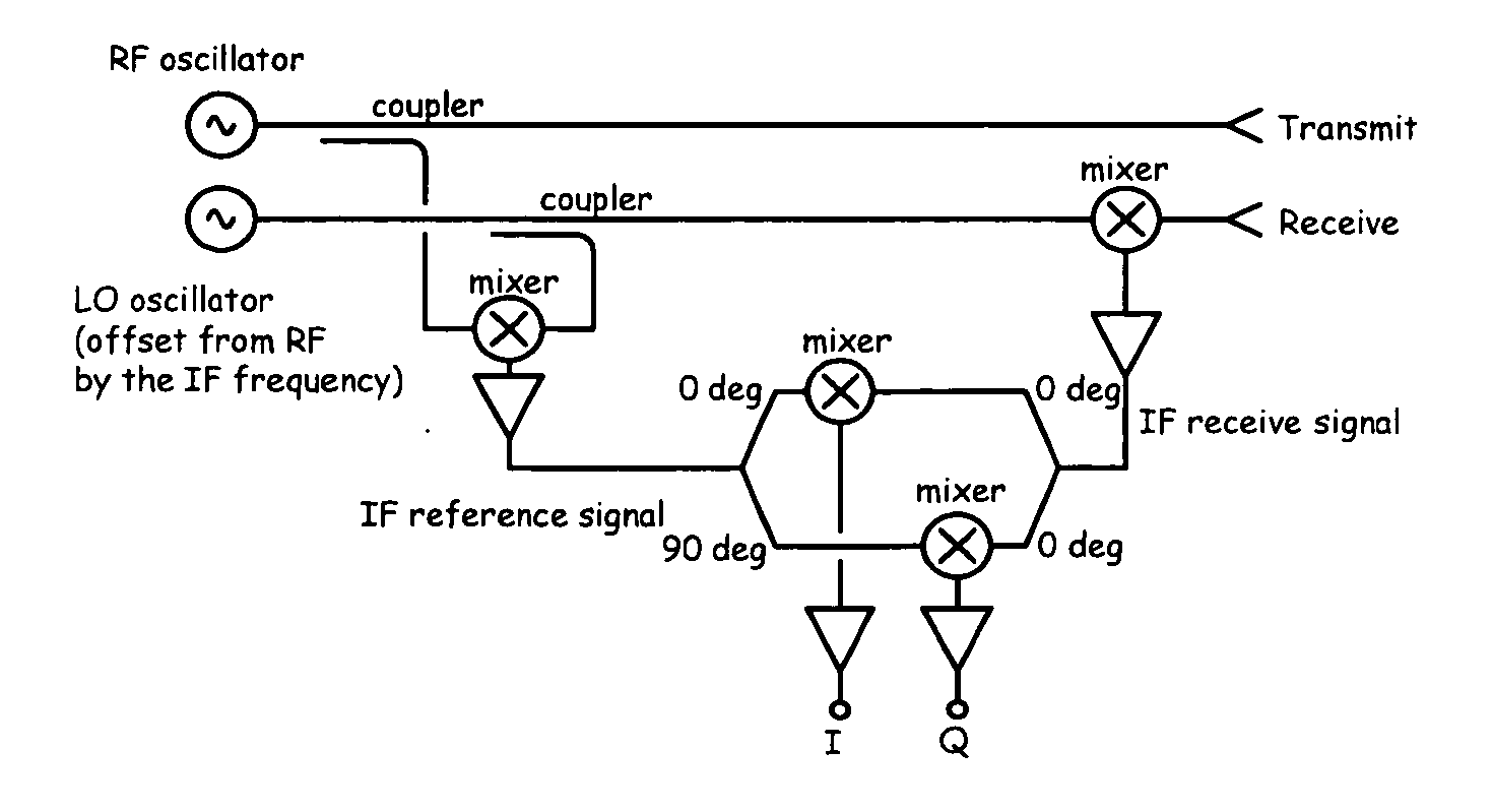
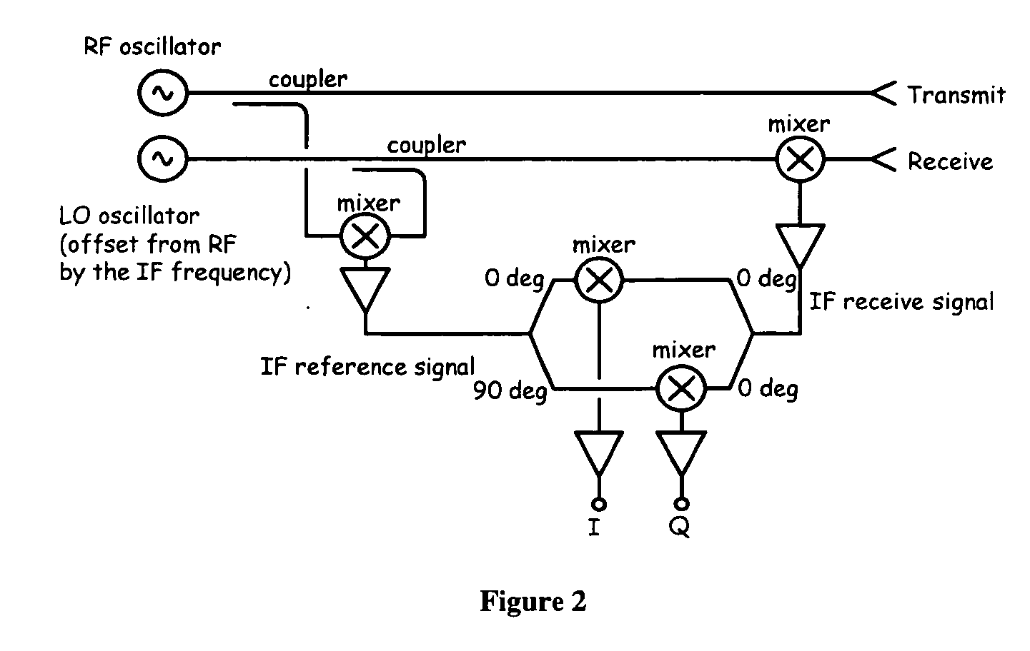
  • Holographic arrays for multi-path imaging artifact reduction
  • Holographic arrays for multi-path imaging artifact reduction
  • Holographic arrays for multi-path imaging artifact reduction

Examples


Embodiment Construction

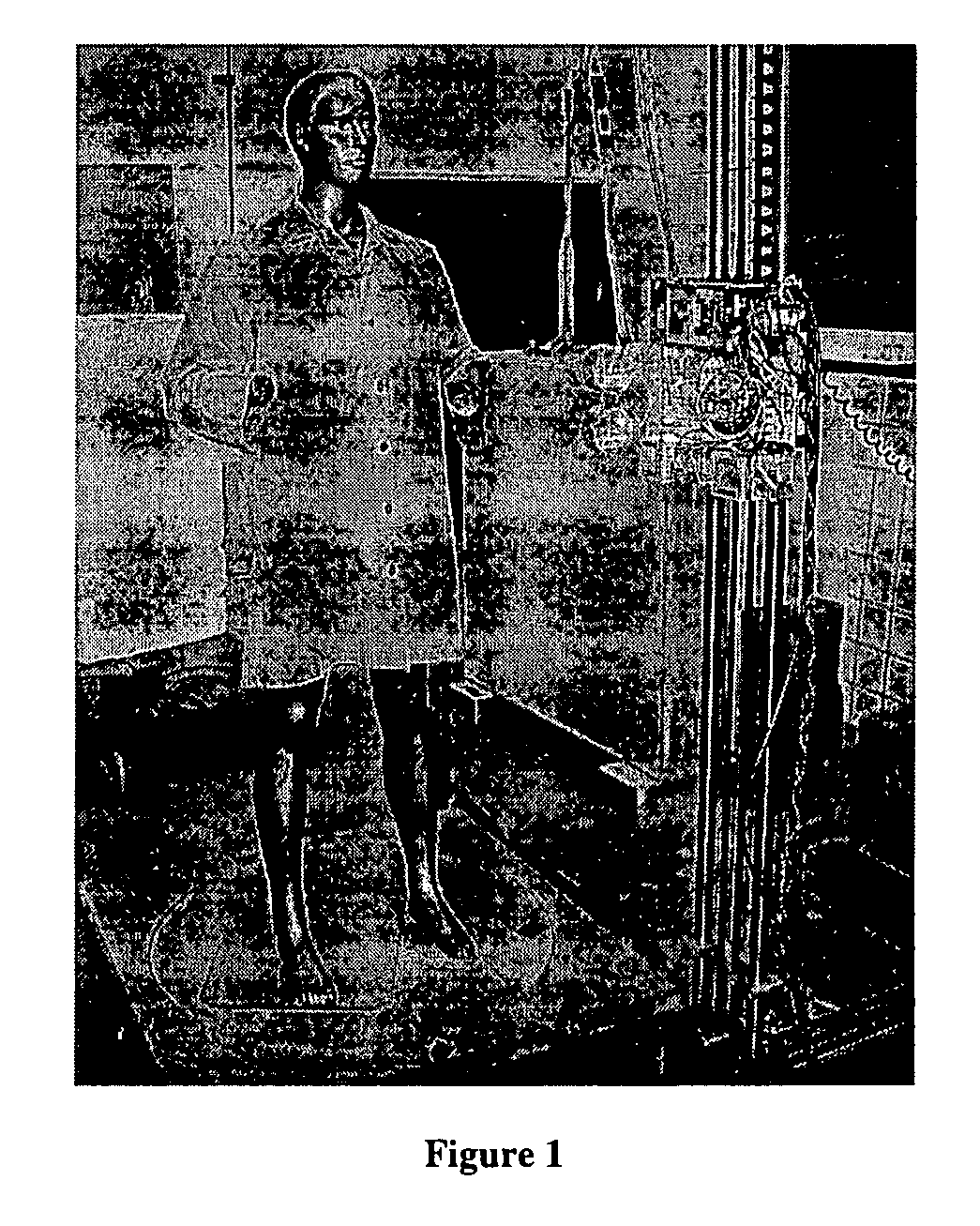
[0034] An experiment was conducted to demonstrate the ability of the present invention to remove artifacts created from multiple reflections of an imaging system imaging a mannequin. Circular polarimetric imaging was employed to obtain additional information from the target, which was then used to remove those features.

[0035] Circularly polarized waves incident on relatively smooth reflecting targets are typically reversed in their rotational handedness, e.g. left-hand circular polarization (LHCP) is reflected to become right-hand circular polarization (RHCP). An incident wave that is reflected twice (or any even number) of times prior to returning to the transceiver, has its handedness preserved. Sharp features, such as wires and edges, tend to return linear polarization, which can be considered to be a sum of both LHCP and RHCP. These characteristics are exploited by the present invention by allowing differentiation of smooth features, such as the body, and sharper features such ...


PUM


Abstract

A method and apparatus to remove human features utilizing at least one transmitter transmitting a signal between 200 MHz and 1 THz, the signal having at least one characteristic of elliptical polarization, and at least one receiver receiving the reflection of the signal from the transmitter. A plurality of such receivers and transmitters are arranged together in an array which is in turn mounted to a scanner, allowing the array to be passed adjacent to the surface of the item being imaged while the transmitter is transmitting electromagnetic radiation. The array is passed adjacent to the surface of the item, such as a human being, that is being imaged. The portions of the received signals wherein the polarity of the characteristic has been reversed and those portions of the received signal wherein the polarity of the characteristic has not been reversed are identified. An image of the item from those portions of the received signal wherein the polarity of the characteristic was reversed is then created.

Description

STATEMENT REGARDING FEDERALLY SPONSORED RESEARCH OR DEVELOPMENT [0001] This invention was made with Government support under Contract DE-AC05-76RL01830 awarded by the U.S. Department of Energy. The Government has certain rights in the invention.CROSS-REFERENCE TO RELATED APPLICATIONS [0002] Not Applicable BACKGROUND OF THE INVENTION [0003] Active and passive millimeter-wave imaging systems have been demonstrated to have the capability to penetrate clothing and produce images of the person underneath the clothing, together with a wide variety of concealed threats including explosives, handguns, and knives. Examples of such systems are found in the following references. The entire text of these references, and all other papers, publications, patents, or other written materials disclosed herein are hereby incorporated into this specification in their entirety by this reference. [0004] 1. Sheen, D. M., D. L. McMakin, and T. E. Hall, Three-dimensional millimeter-wave imaging for conceale...

Claims


Application Information

Patent Timeline
Patent Type & Authority Applications(United States)
IPC IPC(8): G01S13/89
CPCG01S7/026H01Q1/22G01S13/89
Inventor MCMAKIN, DOUGLAS L.SHEEN, DAVID M.HALL, THOMAS E.
Owner BATTELLE MEMORIAL INST
Learn More