
Water activated safety light and flotation device using same

a technology of safety light and flotation device, which is applied in the direction of life-saving, vessel safety, visible signalling system, etc., can solve the problems of difficult to locate in the best of circumstances, severely hamper rescue efforts, and failure to locate and extract survivors from the water quickly

Active Publication Date: 2007-09-06
9609385 CANADA INC
View PDF5 Cites 19 Cited by
  • Summary
  • Abstract
  • Description
  • Claims
  • Application Information

AI Technical Summary

Benefits of technology

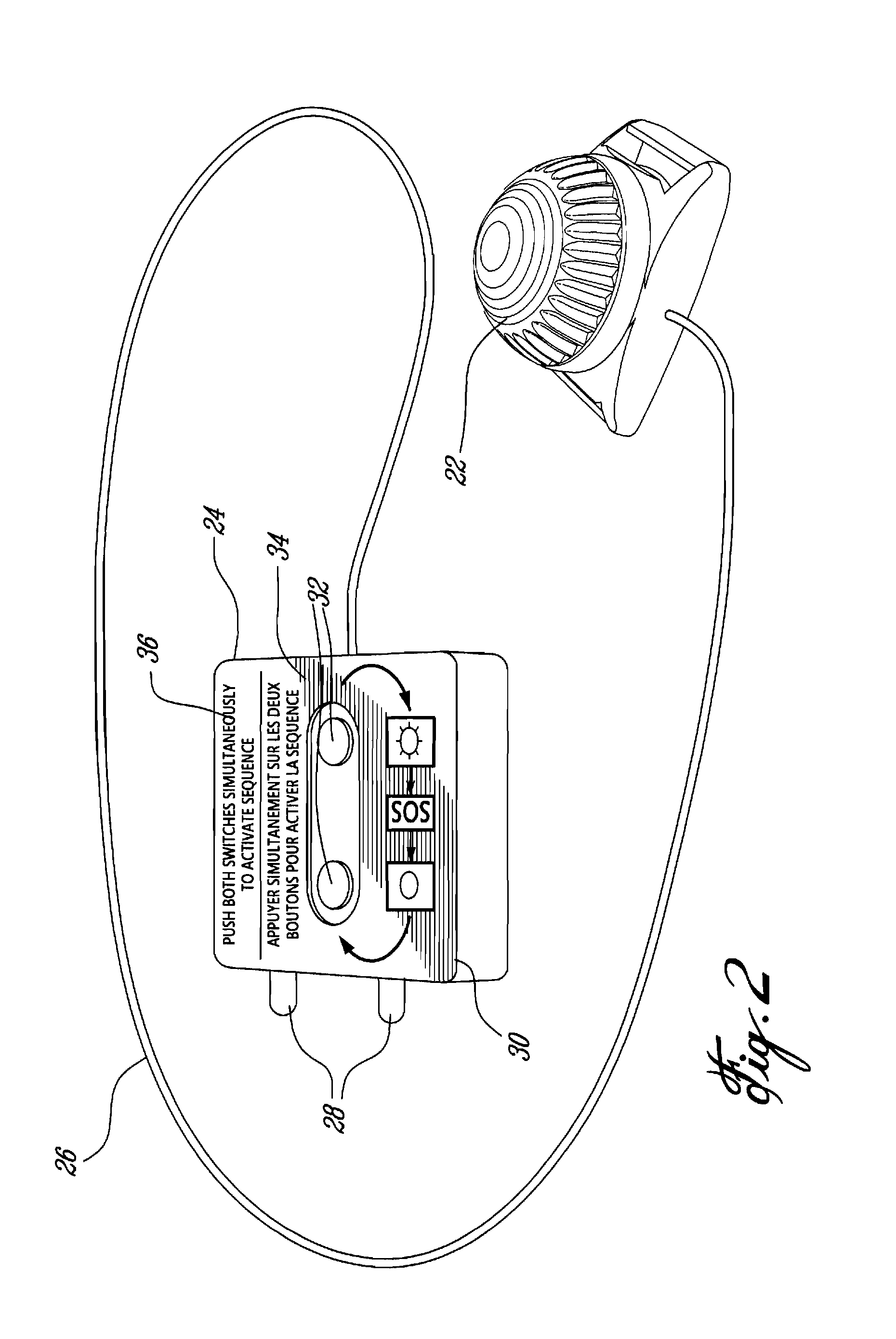
[0007] In order to address the above and other drawbacks, there is provided a method for changing a mode of a light source attached to a flotation device and comprised of at least one light from a first mode to a second mode. The method comprises providing a control panel on the flotation device, wherein the panel is accessible and wherein the control panel comprises at least two switches, and depressing the switches substantially simultaneously.
[0008] There is also provided a method for user control of a light source, the light source adapted for use with a conductive fluid. The method comprises providing a water activated switch and at least one user activated switch, illuminating the light source when the water activated switch is submersed in the conductive fluid, extinguishing the light source when the at least one user activated switch is depressed by the user, removing the water activated switch from the conductive fluid for a period of time and resubmersing the water activated switch in the conductive fluid. When the light is illuminated following the resubmersing act provided the period of time is greater than a predetermined period of time.
[0009] Additionally, there is provided a flotation device comprising a light source attached to the flotation device, a water activated switch, wherein the light source is illuminated when the water activated switch is submersed in the water and a control panel comprised of at least one user activated switch. When the light source is extinguished when the user activated switch is depressed, the control panel having instructions printed thereon.

Problems solved by technology

Persons who become stranded in large bodies of water due to boat mishaps or the like are in the best of circumstances difficult to locate.
This situation is aggravated by the onset of wave action or darkness which can severely hamper rescue efforts, especially if these are being carried out from the air and over large areas.
Additionally, even if a person is equipped with a suitable life vest which ensures that he / she stays afloat even while unconscious, as the onset of hypothermia in even relatively warm bodies of water can be fairly rapid, failure to locate and extract survivors from the water quickly can have dire results.
One drawback of these prior art devices is that they only function when in contact with water.
Another drawback of these prior art devices is that no means are provided to extinguish the light source (for example, during daytime when the light is more or less invisible) and as a result, the batteries of such prior art devices become quickly depleted.
One drawback of these prior art devices is that the toggle switch is easy to engage, which in some cases may lead to the flashing light source being inadvertently disconnected from the battery pack.
Still another drawback is that such prior art devices uses either incandescent bulbs which are inherently fragile, or zenon strobes which are not suitable for use as steady state light sources.
One other drawback is that if the flashing light source is deactivated using the toggle switch and the wearer leaves the water for a period of time, the water activated switch does not reactivate the flashing light source.
As a result, if the wearer subsequently re-enters the water, the flashing light source will not be illuminated.

Method used


Image

  • Water activated safety light and flotation device using same
  • Water activated safety light and flotation device using same
  • Water activated safety light and flotation device using same

Examples


Embodiment Construction

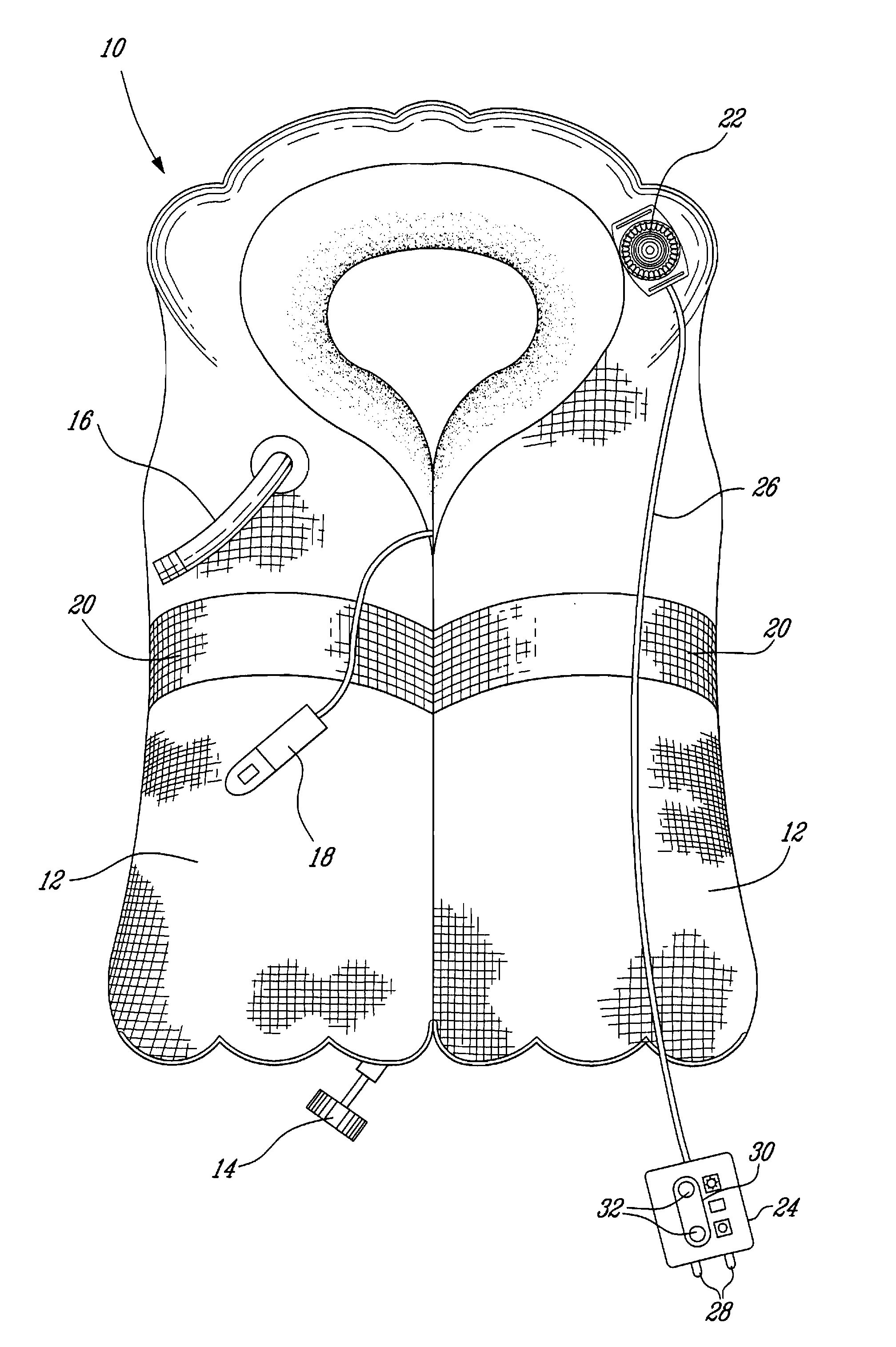
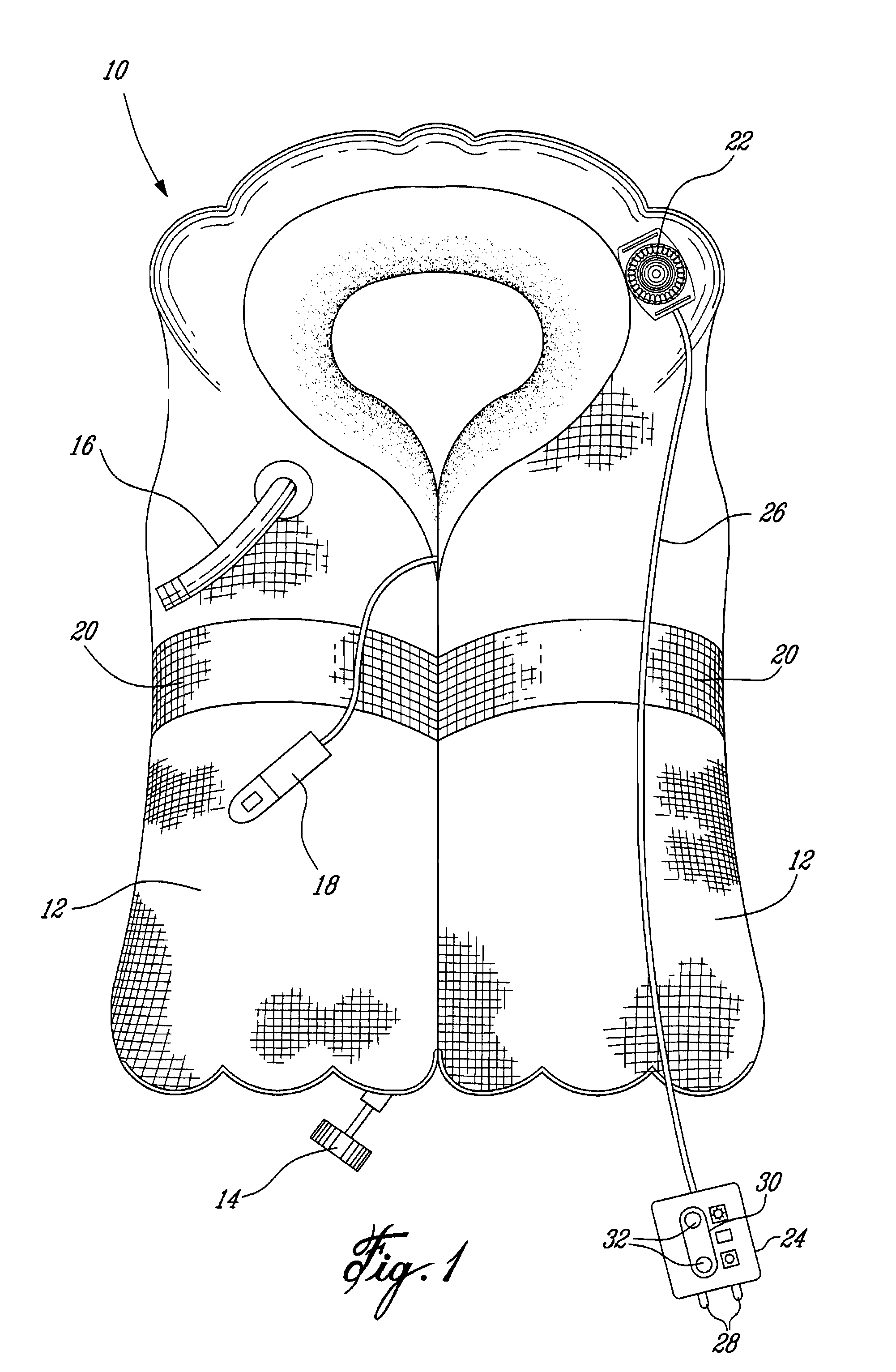
[0015] Referring now to FIG. 1, a life vest in accordance with an illustrative embodiment of the present invention, and generally referred to using the reference numeral 10, will be described. The life vest 10 is comprised of one or more chambers as in 12 which are filled with a buoyant material (not shown). In the case of an inflatable vest, the buoyant material is a gas, such as CO2 or air, which is introduced into the chamber(s) from a cylinder or the like (not shown), typically activated by means of a rip cord 14. Additionally, a back up oral inflation tube 16 is provided in order to maintain buoyancy or inflate the vest 10 when the cylinder is empty or inoperable.

[0016] Still referring to FIG. 1, in order to improve a wearer's chances of being discovered, the outer visible part of the life vest 10 is typically manufactured from a bright material in yellow or day-glow orange. Additionally, the life vest 10 is equipped with a whistle 18 for generating an audible signal, reflecti...


PUM


Abstract

There is disclosed a flotation device such as a life vest or inflatable raft for keeping a user afloat when in water, the flotation device comprising a light source attached to the flotation device, a water activated switch, wherein the light source is illuminated when the water activated switch is submersed in the water, and a control panel mounted to an outer surface of the flotation device and comprised of at least one user activated switch, wherein the light source is extinguished when the user activated switch is depressed, the control panel having instructions printed thereon.

Description

CROSS REFERENCE TO RELATED APPLICATIONS [0001] The present application claims priority from U.S. Provisional Application No. 60 / 778,929 filed on Mar. 6, 2006 the entirety of which is incorporated herein by referenceFIELD OF THE INVENTION [0002] The present invention relates to a water activated safety light and flotation device, such as a life vest or life raft, using same. In particular, the present invention relates to a water activated safety light with manual override including a switch pad to switch between two or more user modes. BACKGROUND TO THE INVENTION [0003] Persons who become stranded in large bodies of water due to boat mishaps or the like are in the best of circumstances difficult to locate. This situation is aggravated by the onset of wave action or darkness which can severely hamper rescue efforts, especially if these are being carried out from the air and over large areas. Additionally, even if a person is equipped with a suitable life vest which ensures that he / sh...

Claims


Application Information

Patent Timeline
Patent Type & Authority Applications(United States)
IPC IPC(8): G08B23/00
CPCB63C9/0005G08B5/36B63C9/20B63C9/1255
Inventor FORD, TIMOTHY D.F.GASCON, STEPHANE
Owner 9609385 CANADA INC
Learn More