
Arrangement for recirculation of exhaust gases of a super-charged internal combustion engine

a technology of exhaust gas and combustion engine, which is applied in the direction of machines/engines, mechanical equipment, non-fuel substance addition to fuel, etc., can solve the problems of relatively large difference between the temperature of the coolant and the temperature of the exhaust gas, and the effectiveness of gaseous cooling medium such as air is usually not particularly effectiv

Inactive Publication Date: 2007-09-06
SCANIA CV AB
View PDF23 Cites 19 Cited by
  • Summary
  • Abstract
  • Description
  • Claims
  • Application Information

AI Technical Summary

Benefits of technology

[0004] The object of the invention is to provide an arrangement which effects recirculation of exhaust gases in a supercharged combustion engine in such a way that the recirculation of exhaust gases does not result in the combustion engine's performance being inferior to that of a corresponding combustion engine not provided with recirculation of exhaust gases.
[0006] According to a preferred embodiment of the present invention, said first medium is ambient air. Ambient air is at all times an available medium and needs no complicated equipment to cause it to flow through the first cooler. Using ambient air as cooling medium makes it possible for the exhaust gases to be cooled down to a level close to the temperature of the ambient air. The same cooling medium is therefore used in the first cooler as in a conventional charge air cooler for cooling of compressed air. This means that exhaust gases can be cooled to the same level as the compressed air in a conventional charge air cooler. The arrangement is used with advantage in a vehicle which is powered by the combustion engine. The result is a natural flow of ambient air through the first cooler during operation of the vehicle. A cooling fan may possibly be incorporated to guarantee the air flow through the first cooler.
[0007] According to a preferred embodiment of the present invention, the arrangement comprises a second cooler adapted to cooling the exhaust gases in the return line. A gaseous cooling medium such as air is usually not particularly effective as regards carrying heat away in a cooler. There are substantially more effective coolers than those which are cooled by air. It is therefore advantageous to use such a more effective second cooler for cooling the hot exhaust gases as a first step before they are cooled by the first cooler. Said second cooler is preferably cooled by a liquid medium. A liquid medium usually provides much more effective cooling than a gaseous medium. A liquid-cooled cooler which has the same cooling capacity as an air-cooled cooler can therefore be made considerably smaller. When such a liquid-cooled second cooler is incorporated in the return line, the temperature of the exhaust gases can be lowered in an effective manner as a first step. A significantly lower cooling capacity is therefore required of the first cooler and the latter can therefore be made significantly smaller. The liquid medium may be adapted to circulating in a cooling system which is also adapted to cooling the combustion engine. In such cases the existing coolant in the vehicle's cooling system is thus used for cooling the exhaust gases as a first step. Although the temperature of the coolant will be higher than the temperature of the ambient air, the result is a relatively large difference between the temperature of the coolant and the temperature of the exhaust gases. The coolant in said second cooler can thus provide effective cooling of the exhaust gases.
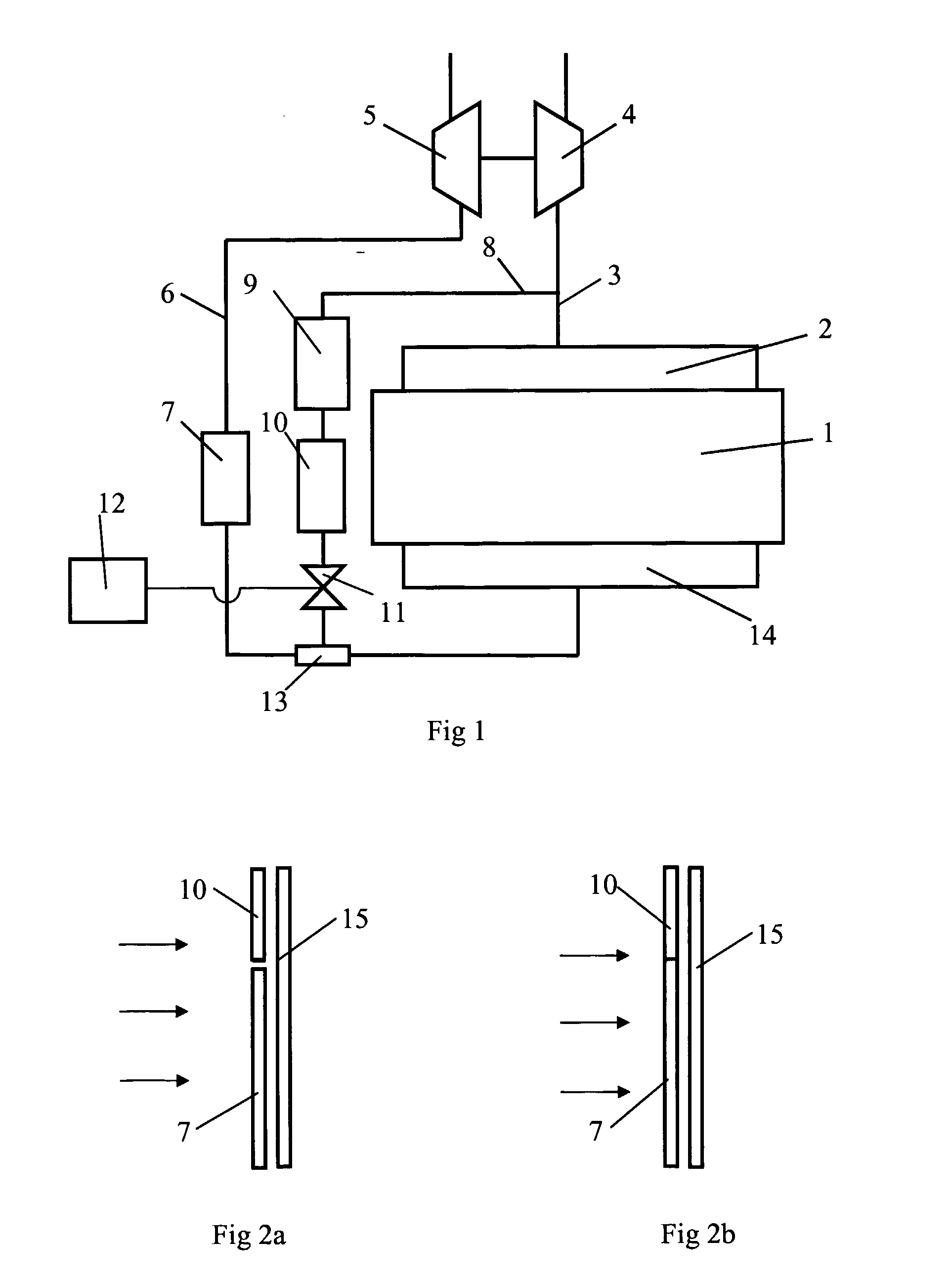
[0008] According to another preferred embodiment, the arrangement comprises a third cooler for cooling the air in the inlet line before it is mixed with the exhaust gases from the return line. Such a third cooler is with advantage air-cooled and may be a conventional charge air cooler. With advantage, the first cooler and the third cooler are positioned close to one another. As both the first cooler and the third cooler are air-cooled, they can be arranged at a substantially common location where ambient air flows through them. In such cases the first cooler and the third cooler may form an integrated unit. The result is a composite modular cooler unit which is easy to fit in the vehicle. The first cooler and the third cooler may take the form of flat cooler elements which each have a main extent in one plane, whereby the first cooler and the third cooler have an extent in a substantially common plane. In such cases the cooling air flows through the coolers in a direction substantially perpendicular to said plane.

Problems solved by technology

A gaseous cooling medium such as air is usually not particularly effective as regards carrying heat away in a cooler.
Although the temperature of the coolant will be higher than the temperature of the ambient air, the result is a relatively large difference between the temperature of the coolant and the temperature of the exhaust gases.

Method used


Image

  • Arrangement for recirculation of exhaust gases of a super-charged internal combustion engine
  • Arrangement for recirculation of exhaust gases of a super-charged internal combustion engine

Examples


Embodiment Construction

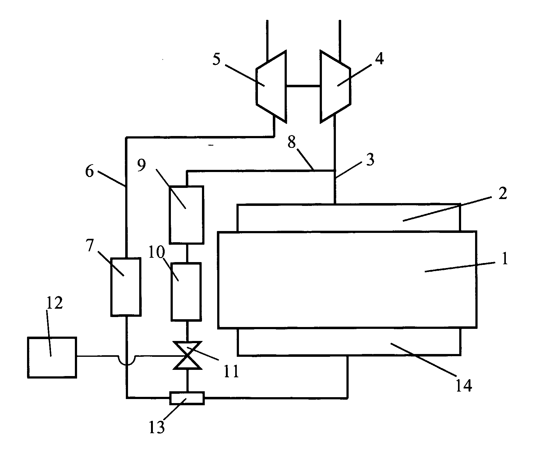
[0014]FIG. 1 depicts schematically an arrangement for recirculation of exhaust gases in a supercharged combustion engine. The combustion engine is in this case a diesel engine 1. Such recirculation is usually called EGR (Exhaust Gas Recirculation). Adding exhaust gases to the compressed air which is led to the engine's cylinders lowers the combustion temperature and hence also the content of nitrogen oxides (NOx) which are formed during the combustion processes. The diesel engine 1 may for example be intended to power a heavy vehicle. The exhaust gases from the cylinders of the diesel engine 1 are led via an exhaust manifold 2 to an exhaust line 3. The exhaust gases in the exhaust line 3, which are at above atmospheric pressure, are led to a turbine 4. The turbine 4 is thus provided with driving power which is transferred, via a connection, to a compressor 5. The compressor 5 compresses the air which is led into the inlet line 6. A charge air cooler 7 is arranged in the inlet line 6...


PUM


Abstract

An arrangement for recirculation of exhaust gases in a supercharged combustion engine. The arrangement includes an exhaust line operable to lead exhaust gases out from the combustion engine, an inlet line operable to lead air at above atmospheric pressure to the combustion engine, a return line which comprises a connection to the exhaust line and a connection to the inlet line, so that via the return line it is possible to recirculate exhaust gases from the exhaust line to the inlet line. A first cooler incorporated in the return line for cooling the exhaust gases in the return line before they are mixed with the air in the inlet line. The exhaust gases in the first cooler are cooled by a first medium which is at a temperature substantially corresponding to the temperature of the surroundings.

Description

BACKGROUND TO THE INVENTION, AND STATE OF THE ART [0001] The present invention relates to an arrangement for recirculation of exhaust gases in a supercharged combustion engine according to the preamble of claim 1. [0002] The technique known as EGR (Exhaust Gas Recirculation) is a known way of leading part of the exhaust gases from a combustion process in a combustion engine back, via a return line, to an inlet line for supply of air to the combustion engine. A mixture of air and exhaust gases is thus supplied via the inlet line to the engine's cylinders in which the combustion takes place. The addition of exhaust gases to the air causes a lower combustion temperature resulting inter alia in a reduced content of nitrogen oxides NOx in the exhaust gases. This technique is applied in both Otto engines and diesel engines. [0003] The amount of air which can be supplied to a supercharged combustion engine depends on the pressure of the air but also on the temperature of the air. Supplying...

Claims


Application Information

Patent Timeline
Patent Type & Authority Applications(United States)
IPC IPC(8): F02B29/04F02B33/44F02MF02M25/07
CPCF02B29/0425F02B29/0475F02M25/0707Y02T10/146F02M25/0731F02M25/0732Y02T10/121F02M25/073F02M26/05F02M26/27F02M26/28F02M26/24Y02T10/12
Inventor PELZ, MAGNUSSKOG, HENRIKSARBY, HAKAN
Owner SCANIA CV AB
Learn More