
Circuit diagram drafting system and method and computer program product

a circuit diagram and drafting system technology, applied in the field of circuit diagram drafting system and method to computer program products, can solve the problems of circuit design work almost never being completed at one go, and large amount of time and labor required for the above work, so as to reduce the time and labor involved in verification work and facilitate the verification work at the time of attaching a line marker

Active Publication Date: 2007-08-30
FUJITSU LTD
View PDF1 Cites 2 Cited by
  • Summary
  • Abstract
  • Description
  • Claims
  • Application Information

AI Technical Summary

Benefits of technology

[0007] The present invention was made to solve the above problems and has as its object the provision of a circuit diagram drafting system and method and computer program product enabling the circuit verification work to be efficiently and reliably performed in a manner corresponding to the circuit.
[0014] The present invention, being configured in the above way, can select a set unit of a line marker and attach a line marker corresponding to the characteristics of the circuit prepared. Further, even if a circuit design is reworked, since the verified connections have line markers attached, the time and labor involved in verification work can be reduced. Further, since the connected terminals can be jumped to in the display, the verification work at the time of attaching a line marker becomes easy.

Problems solved by technology

As a result, the drafted circuit diagrams have also become huge.
However, circuit design work almost never is completed at one go.
Therefore, there was the problem that an extremely large amount of time and labor were required for the above work.
However, since the techniques described in these publications perform processing for automatically extracting connection paths between the circuit elements, when the circuits checked were gigantic in size, there were problems in the efficiency, reliability, and flexibility of the verification work of the circuits.

Method used


Image

  • Circuit diagram drafting system and method and computer program product
  • Circuit diagram drafting system and method and computer program product
  • Circuit diagram drafting system and method and computer program product

Examples


Embodiment Construction

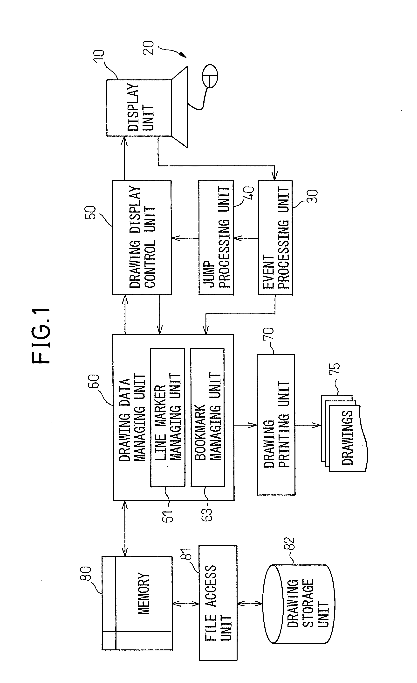
[0047] Below, embodiments of the present invention will be explained with reference to the drawings. FIG. 1 shows the system configuration for line marker processing or bookmark processing of a circuit diagram drafting system according to one embodiment of the present invention. The operator uses a keyboard or mouse or other input device 20 while referring to a display unit, that is, a screen 10, to draft a circuit diagram. This is stored through a file access unit 81 in a hard disk or other drawing storage unit 82 as a drawing file.

[0048] When the drafted drawing data is to be verified, the drawing file storing the drawing data is taken out from the drawing storage unit 82 through the file access unit 81 and the drawing data is loaded in the memory. That drawing data is sent through a drawing data managing unit 60 for attaching and managing line markers, bookmarks, etc. to a drawing display control unit 50 and displayed on the display unit 10.

[0049] In the present embodiment, whe...


PUM


Abstract

A circuit diagram drafting system for drafting a circuit diagram comprised of a plurality of circuit components and connections connecting terminals of the circuit components, the circuit diagram drafting system provided with a display unit for displaying the circuit diagram and a managing unit for attaching and managing a line marker on connections of the circuit diagram displayed on the display unit based on a set unit selected from a predetermined plurality of line marker set units, and a circuit diagram drafting method and computer program relating to the same.

Description

BACKGROUND OF THE INVENTION [0001] 1. Field of the Invention [0002] The present invention relates to a circuit diagram drafting system and method and to a computer program product for the same, more particularly relates to a circuit diagram drafting system and method and a computer program for the same enabling easy confirmation of connections of the drafted circuit diagram. [0003] 2. Description of the Related Art [0004] When electronic equipment is designed, the logic of the designed electronic equipment, that is, the connections among the components forming the electronic equipment, are expressed by a circuit diagram. In recent years, components of electronic equipment have been made smaller in size and have been arranged at a higher density. As a result, the drafted circuit diagrams have also become huge. The hardware or software for drafting circuit diagrams is provided with a design rule check function for verifying if there are any omissions in the connections of the drafted ...

Claims


Application Information

Patent Timeline
IPC IPC(8): G06F17/50
CPCG06F17/5045G06F30/30
Inventor KUMAGAI, YOSHITOMO
Owner FUJITSU LTD
Learn More