
Base station and radio communication method

a radio communication and base station technology, applied in radio transmission, power management, electrical equipment, etc., can solve the problems of reducing utilization efficiency and increasing interference from neighboring base stations

Inactive Publication Date: 2007-08-30
KK TOSHIBA
View PDF0 Cites 162 Cited by
  • Summary
  • Abstract
  • Description
  • Claims
  • Application Information

AI Technical Summary

Benefits of technology

[0008] According to an aspect of the present invention, there is provided with a base station which carries out radio communication with mobile stations, a communication area of which partially overlaps with a communication area of one or more other base station, comprising:

Problems solved by technology

When neighboring base stations transmit data to user terminals in their respective cells using an identical frequency and same time slot, if some user terminal is located in the neighborhood of a cell boundary, there is a problem that interference from the neighboring base stations increases considerably.
For these reasons, it is an issue how all base stations reuse an identical frequency to construct a cellular communication system with high frequency utilization efficiency.

Method used


Image

  • Base station and radio communication method
  • Base station and radio communication method
  • Base station and radio communication method

Examples


Embodiment Construction

[0039] Hereinafter, this embodiment will be explained in detail with reference to the attached drawings.

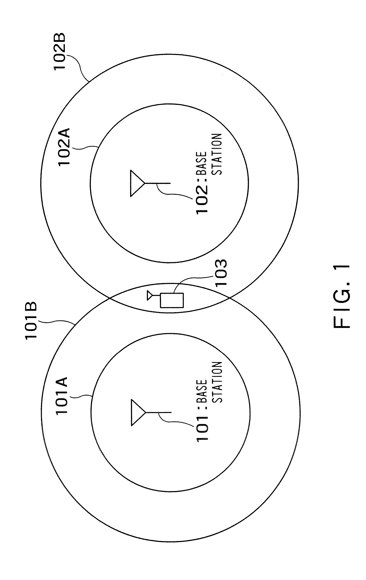
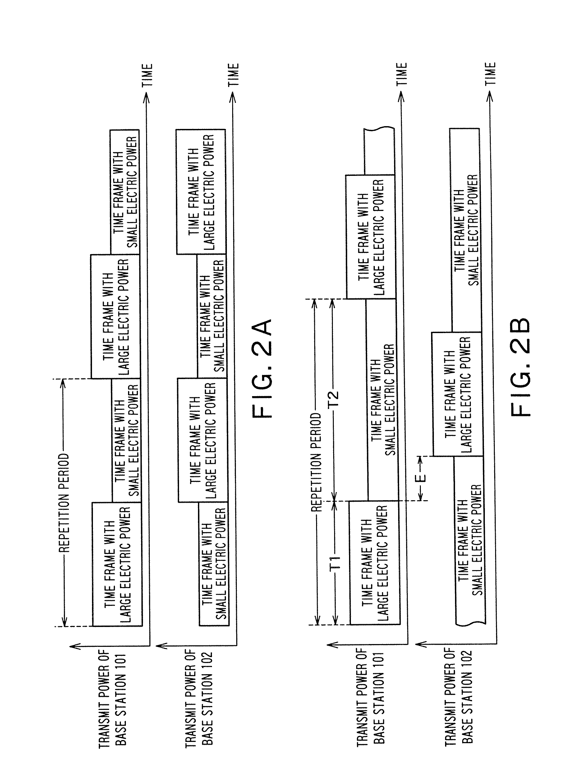
[0040]FIG. 1 shows an embodiment of a cellular communication system according to the present invention. FIG. 2A and FIG. 2B illustrate time frame transmit power control carried out by the base stations in FIG. 1.

[0041] In FIG. 1, a base station 101 and a base station 102 have the function of transmitting time frames with large electric power which covers a whole cell and time frames with small electric power which covers only the neighborhood of the base stations.

[0042] Reference numeral 101A denotes a cover range (communication area) when the base station 101 transmits time frames with small electric power and 101B denotes a cover range when the base station 101 transmits time frames with large electric power. In the same way, reference numeral 102A denotes a cover range when the base station 102 transmits time frames with small electric power and 102B denotes a cover range wh...


PUM


Abstract

There is provided with a base station which carries out radio communication with mobile stations, including: a frame generation section configured to successively generate time frames to be transmitted to the mobile stations; a storage configured to store transmit power information specifying transmission power to be applied for each of a predetermined number of time frames being successive as one of first transmit power covering a whole of the communication area, second to nth (n is an integer equal to or greater than 2) transmit power covering areas smaller than the whole of the communication area; a transmit power control section configured to control transmit power of time frames successively generated by the frame generation section according to the transmit power information in units of the predetermined number of time frames; and a transmission section configured to transmit time frames power-controlled by the transmit power control section.

Description

CROSS-REFERENCE TO RELATED APPLICATIONS [0001] This application is based upon and claims the benefit of priority from the prior Japanese Patent Applications No. 2006-50626 filed on Feb. 27, 2006, the entire contents of which are incorporated herein by reference. BACKGROUND OF THE INVENTION [0002] 1. Field of the Invention [0003] The present invention relates to a base station in a cellular communication system and a radio communication method performed by the base station, and more particularly, to transmit power control over time frames transmitted sequentially from the base station. [0004] 2. Related Art [0005] According to time division multiplexing in a conventional cellular communication system, a base station divides 1 frame into a plurality of time slots and transmits data to a plurality of user terminals (mobile stations) in a cell by using different time slots. When neighboring base stations transmit data to user terminals in their respective cells using an identical freque...

Claims


Application Information

Patent Timeline
Patent Type & Authority Applications(United States)
IPC IPC(8): H04Q7/20H04W52/24
CPCH04W52/245H04W52/325
Inventor BAN, KOICHIRO
Owner KK TOSHIBA
Learn More