
Ceramic/metallic dental abutment

a technology of ceramic/metallic abutments and dental abutments, which is applied in the field of ceramic/metallic abutments, can solve the problems of the metal portion of the abutment beneath the crown becoming exposed, and achieve the effect of avoiding the formation of abutments

Inactive Publication Date: 2007-08-30
ZIMMER DENTAL INC
View PDF19 Cites 22 Cited by
  • Summary
  • Abstract
  • Description
  • Claims
  • Application Information

AI Technical Summary

Benefits of technology

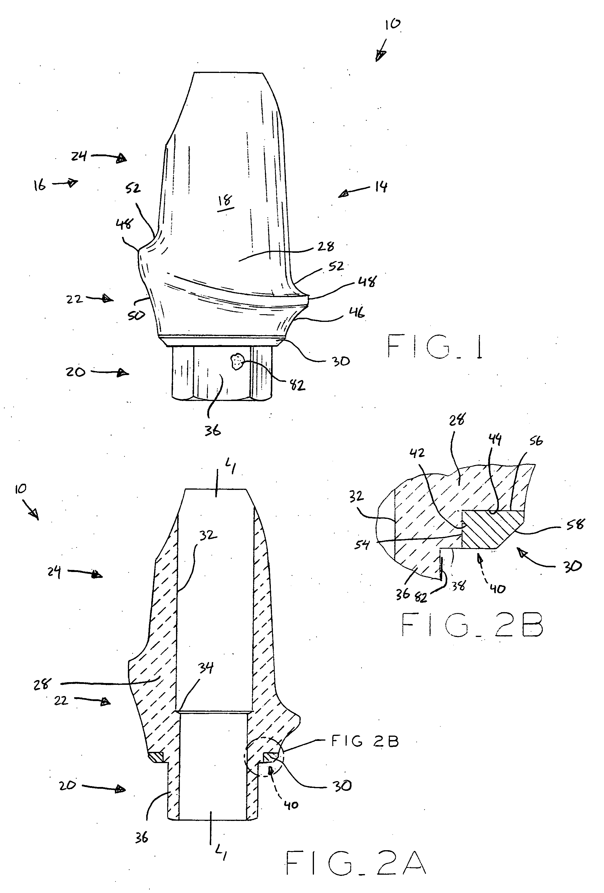
[0012] In one embodiment, the proximal end of the implant includes an annular chamfer disposed at an oblique angle with respect to the longitudinal axis of the implant and abutment, and the implant contact portion of the abutment includes a contact surface disposed at a cooperating angle for engagement with the implant chamfer. The internal polygonal fitting of the implant may be greater in length than the external polygonal fitting of the abutment such that, upon receipt of the external polygonal abutment fitting into the internal polygonal implant fitting, relative rotation between the abutment and implant is prevented while axial loads from the abutment, such as occlusal and / or mastication loads, for example, are transferred to the implant only through the implant contact portion for improved resistance to wear.
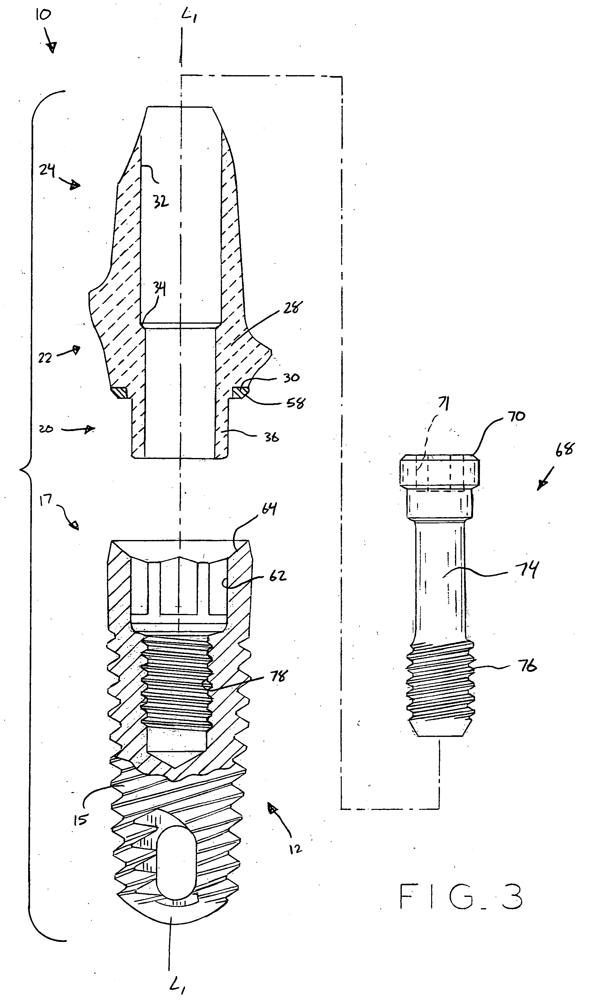
[0015] In a further form thereof, the present invention provides, in combination, a dental implant, including an externally threaded body having a distal end and a proximal end; a bore extending into the proximal end, the bore including a threaded portion and a first anti-rotational interface; and a dental abutment, including a ceramic body portion including a second anti-rotational interface cooperable with the first anti-rotational interface of the implant whereby relative rotation between the abutment and the implant is prevented; and a metal contact portion abuttable with the proximal end of the implant.

Problems solved by technology

However, if recession of the gingival tissue occurs around the implant and abutment after implantation, there is the potential that a portion of the metal of the abutment beneath the crown may become exposed, such that the grey color of the titanium is visible, which is aesthetically disadvantageous.

Method used


Image

  • Ceramic/metallic dental abutment
  • Ceramic/metallic dental abutment
  • Ceramic/metallic dental abutment

Examples


Embodiment Construction

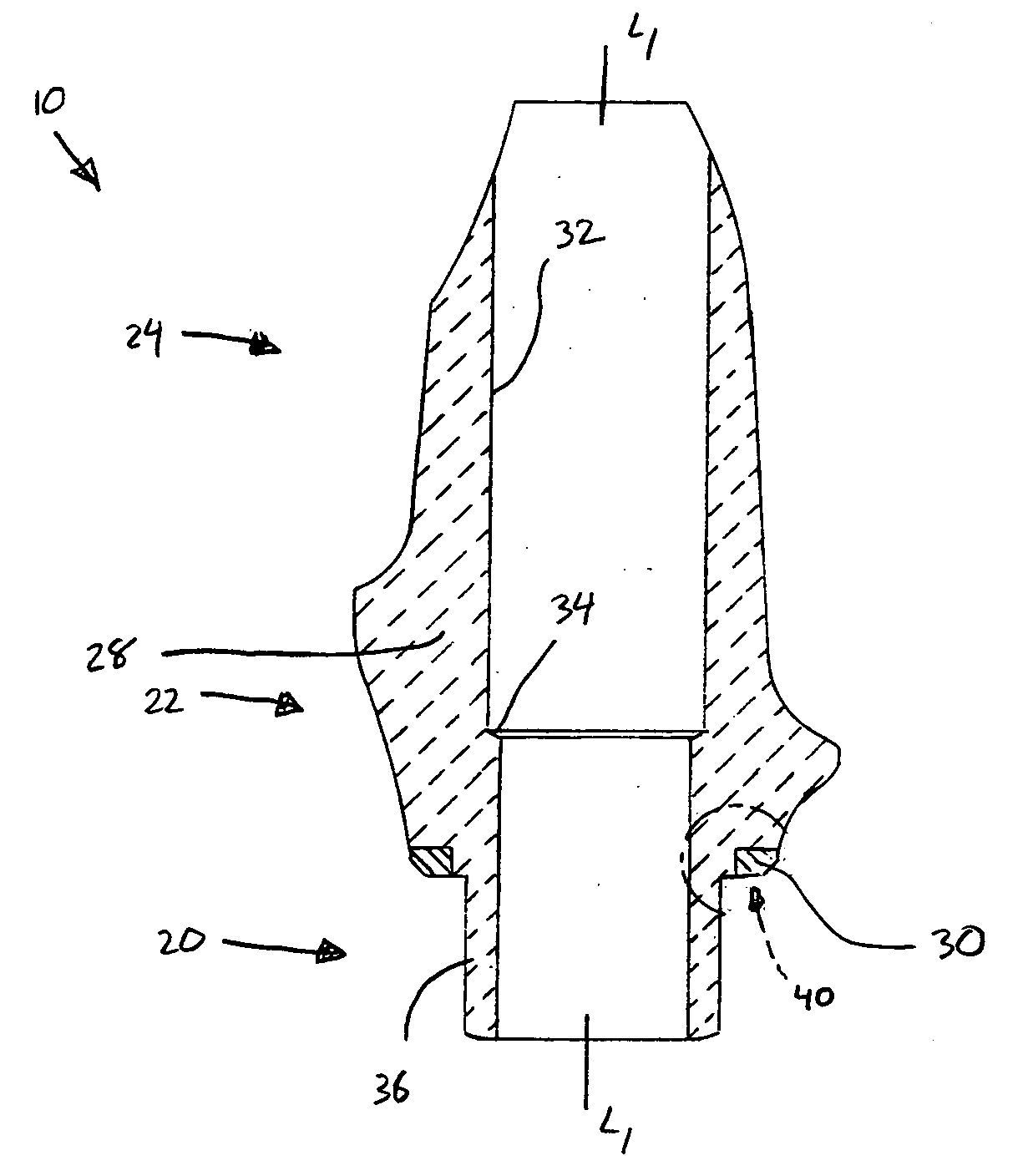
[0025] Referring first to FIGS. 1, 2A, and 2B, a ceramic / metallic dental abutment 10 according to the present invention is shown, which may be used with a dental implant 12, such as that shown in FIGS. 3 and 4 and described below, to provide a prosthetic tooth at an edentulous site in a patient's dentition at which a natural tooth has been lost or damaged. In FIG. 1, an interproximal view of abutment 10 is shown, which includes a facial side 14 and an opposing lingual side 16, as well as a mesial side 18 and an opposing distal side (not visible in FIG. 1). Abutment 10 also generally includes a base region 20 for interfacing with implant 12, an emergence profile region or transgingival region 22 which extends through soft gingival tissue, and a coronal region or supragingival region 24 extending superiorly of transgingival region 22 to which a prosthetic tooth or crown 26 may be attached, as shown in FIG. 4.

[0026] Abutment 10 includes a body portion 28 made of a suitable ceramic mat...


PUM


Abstract

A ceramic / metallic dental abutment for use with an implant, the abutment generally including a ceramic body portion having a base region, a transgingival region, and a supragingival region. The base region includes an anti-rotational implant interface, such as an external polygonal fitting, for engaging a cooperating internal polygonal fitting of an implant to prevent relative rotation between the abutment and the implant. The ceramic abutment body portion additionally includes a metal implant contact portion for contacting the implant and providing a load-bearing, metal-on-metal interface between the abutment and the implant.

Description

BACKGROUND OF THE INVENTION [0001] 1. Field of the Invention. [0002] The present invention relates to dental prosthetics and, in particular, to a ceramic / metallic abutment for use with a dental implant as part of a prosthodontic restoration. [0003] 2. Description of the Related Art [0004] Dental implants are commonly used as anchoring members in prosthodontic restorations to provide prosthetic teeth at one or more edentulous sites in a patient's dentition at which the patient's original natural teeth have been lost or damaged. Typically, known implant systems include a dental implant made from a suitable biocompatible material, such as titanium. The dental implant is typically threaded into a bore which is drilled into the patient's mandible or maxilla at the edentulous site. The implant provides an anchoring member for a dental abutment, which in turn provides an interface between the implant and a dental restoration. The restoration is typically a porcelain crown fashioned accordi...

Claims


Application Information

Patent Timeline
Patent Type & Authority Applications(United States)
IPC IPC(8): A61C8/00
CPCA61C8/005A61C8/0054A61C8/0013A61C8/006A61C8/0068A61C8/0059
Inventor SANCHEZ, RAMIROGERVAIS, CHRISTOPHER M.BASSETT, JEFF A.
Owner ZIMMER DENTAL INC
Learn More