
Liquid crystal display device and back light module therefof

Inactive Publication Date: 2007-08-30
CHUNGHWA PICTURE TUBES LTD
View PDF3 Cites 29 Cited by
  • Summary
  • Abstract
  • Description
  • Claims
  • Application Information

AI Technical Summary

Benefits of technology

[0007] Accordingly, at least one objective of the present invention is to provide a liquid crystal display device capable of minimizing the leakage of light.
[0008] At least another objective of the present invention is to provide a liquid crystal display device having a better image display quality.
[0023] In brief, the liquid crystal display device in the present invention utilizes the light-shielding portion on the rubber frame between the side surface of the light-guiding plate and the metal back plate to block the light coming from the side surface of the light-guiding plate. Hence, the light-shielding portion prevents any light from dispersing externally after reflected from the surface of the metal back plate. As a result, the leakage of light from the periphery of the liquid crystal display device is minimized and the image display quality of the device is improved. In addition, the same reduced leakage of light from the periphery of the liquid crystal display device can be achieved by disposing a light-shielding tape on the side surface of the light-guiding plate or on the metal back plate facing the side surface.

Problems solved by technology

Ultimately, the display quality will be adversely affected.

Method used


Image

  • Liquid crystal display device and back light module therefof
  • Liquid crystal display device and back light module therefof
  • Liquid crystal display device and back light module therefof

Examples


Embodiment Construction

[0030] Reference will now be made in detail to the present preferred embodiments of the invention, examples of which are illustrated in the accompanying drawings. Wherever possible, the same reference numbers are used in the drawings and the description to refer to the same or like parts.

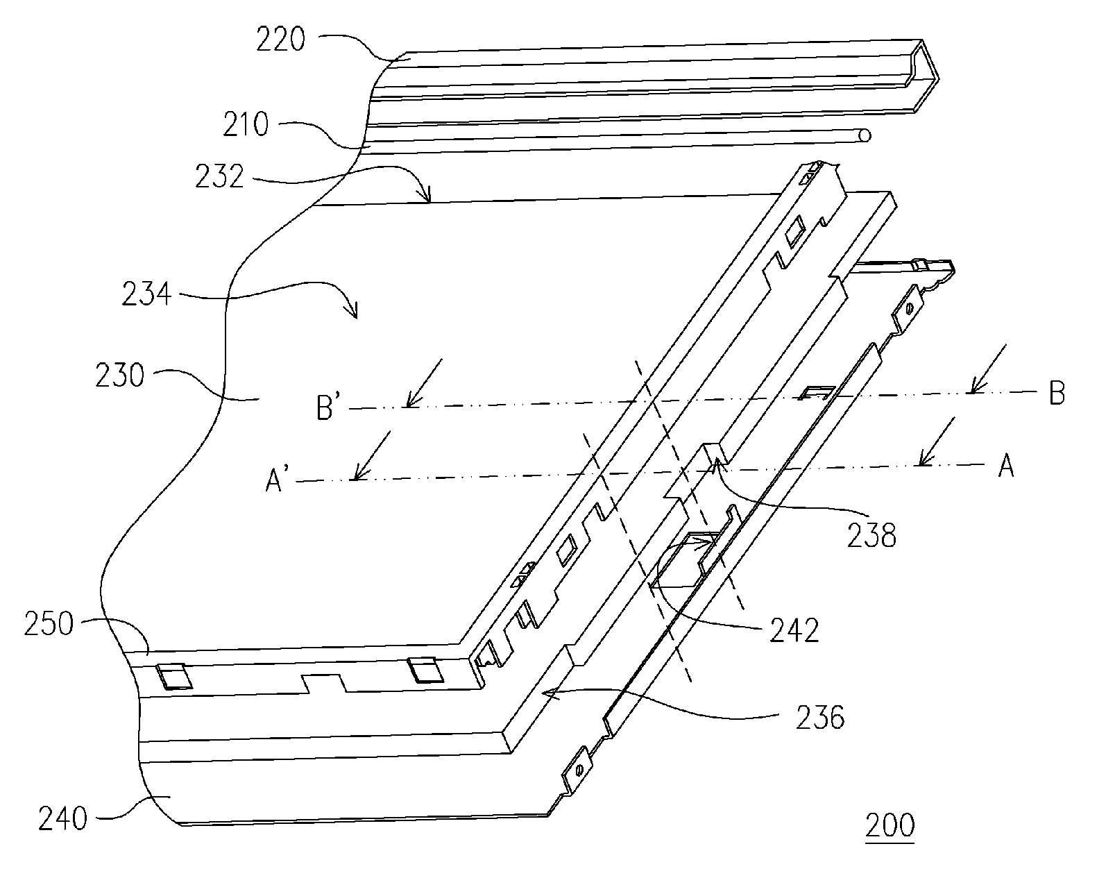
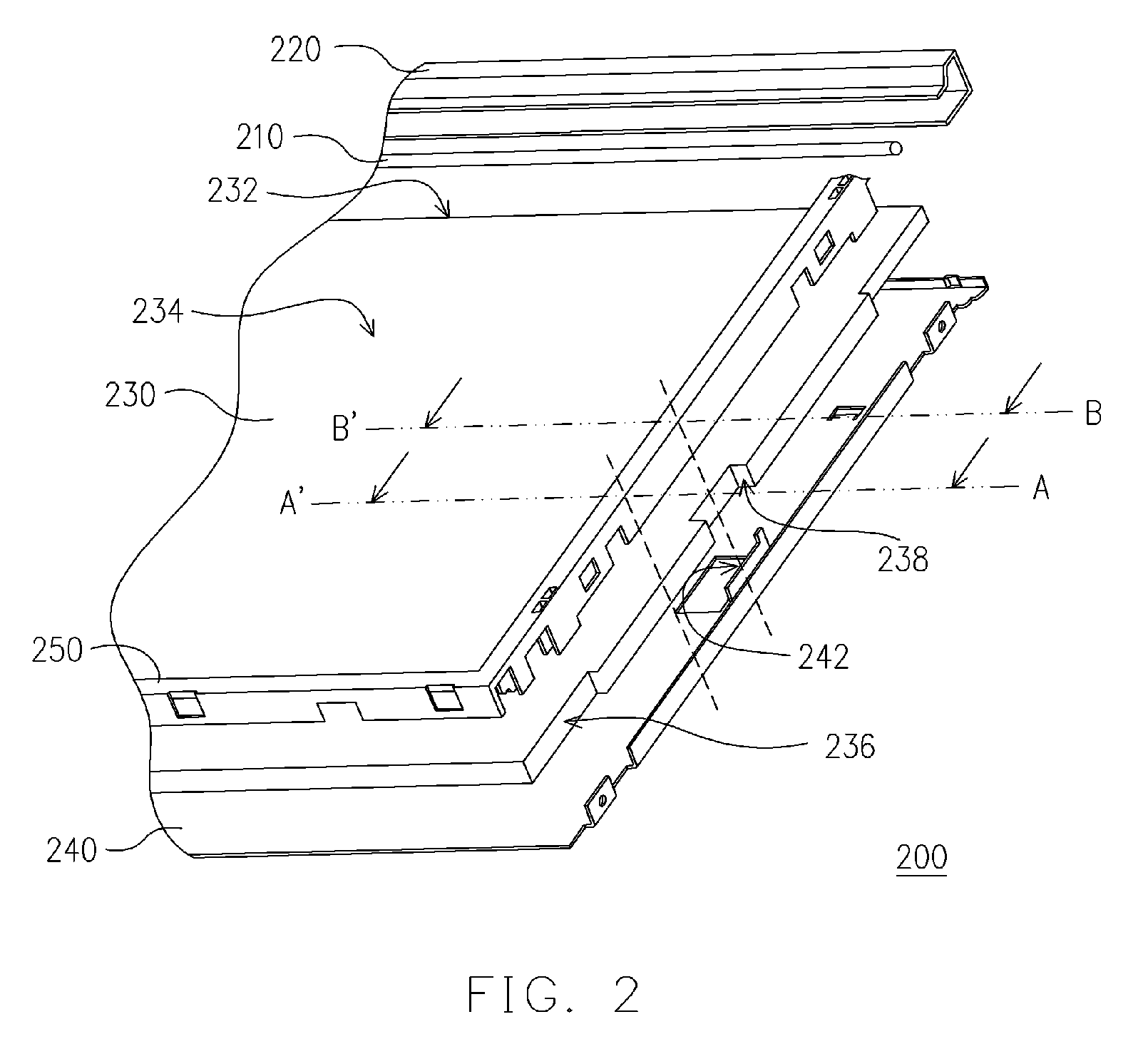
[0031]FIG. 2 is a perspective view showing the dissociated components in a localized portion of a back light module of a liquid crystal display device according to one embodiment of the present invention. As shown in FIG. 2, the back light module 200 in the present invention mainly comprises a light source 210, a reflection cover 220, a light-guiding plate 230, a metal back plate 240 and a rubber frame 250. The light source 210 is disposed inside the reflection cover 220 for emitting light. In the present embodiment, the light source 210 can be a point light source or a linear light source. The linear light source can be a cold cathode fluorescence lamp (CCFL) and the point light source can be a li...


PUM


Abstract

A liquid crystal display (LCD) device includes a back light module, a LCD panel and a front frame. The back light module includes a metal back plate, a light-guiding plate, a reflection cover, a light source and a rubber frame. The light-guiding plate and the reflection cover are disposed inside the metal back plate, and the light-guiding plate has a light incident surface, a light emission surface and a side surface connected to the light emission surface. The reflection cover is located beside the light incident surface, and the light source is disposed therein. The rubber frame is disposed on the metal back plate and includes a body and a light-shielding portion connected thereof. The light-shielding portion is disposed between the side surface and the metal back plate. The front frame and the metal back plate are assembled together and together with the rubber frame, clamp the LCD panel.

Description

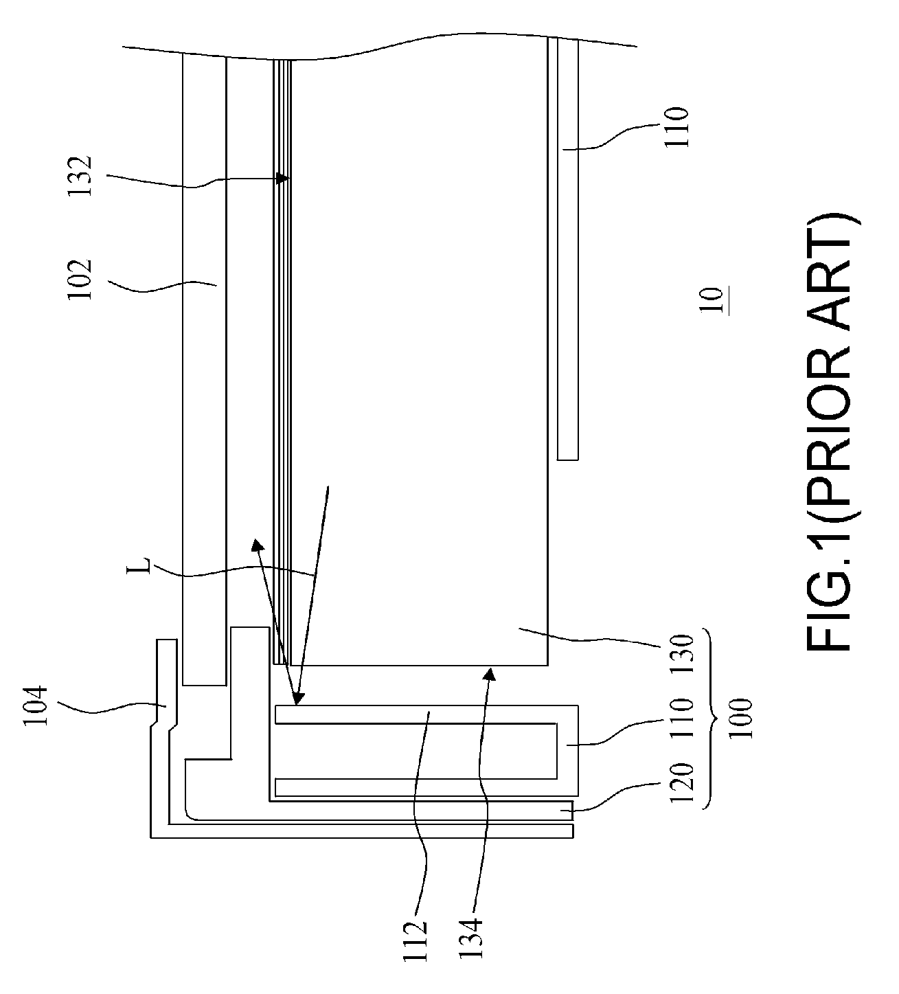
BACKGROUND OF THE INVENTION [0001] 1. Field of the Invention [0002] The present invention relates to a display device. More particularly, the present invention relates to a liquid crystal display that can minimize the leakage of light. [0003] 2. Description of the Related Art [0004] Following the rapid progress in video broadcasting and communication technology, liquid crystal display devices have been used as a display screen in many types of consumer produces including the mobile phones, the notebook computers, the personal computers and the personal digital assistants. Furthermore, with the advantages of light weight, small volume, low working voltage, low power consumption and low level of radiation, liquid crystal display devices have gradually become the mainstream display products. [0005]FIG. 1 is a schematic cross-sectional view of a conventional liquid crystal display device. As shown in FIG. 1, the conventional liquid crystal display device 10 comprises a back light module...

Claims


Application Information

Patent Timeline
IPC IPC(8): G02F1/1333
CPCG02B6/0088
Inventor HSU, WEI-CHENFAN, CHIA-JUNGWANG, YAO-TUNG
Owner CHUNGHWA PICTURE TUBES LTD
Learn More