
Angular velocity sensor and method for operating the same

a technology of angular velocity sensor and angular velocity, which is applied in the direction of variable capacitor, turn-sensitive devices, instruments, etc., can solve the problems of inability to achieve satisfactory canceling effect and output noise of gyro sensor

Inactive Publication Date: 2007-08-30
DENSO CORP +1
View PDF10 Cites 9 Cited by
  • Summary
  • Abstract
  • Description
  • Claims
  • Application Information

AI Technical Summary

Benefits of technology

[0010]In the above sensor, the output caused by an external acceleration is sufficiently cancelled, so that the output attributed to the acceleration is minimized.
[0012]In the above method, the output caused by an external acceleration is sufficiently cancelled, so that the output attributed to the acceleration is minimized.

Problems solved by technology

This output becomes noise for the gyro sensor, which ought to detect the angular velocity.
In the above case, it has been verified, however, that the method cannot attain a satisfactory canceling effect, but that it generates the output ascribable to the external acceleration.

Method used


Image

  • Angular velocity sensor and method for operating the same
  • Angular velocity sensor and method for operating the same
  • Angular velocity sensor and method for operating the same

Examples


Embodiment Construction

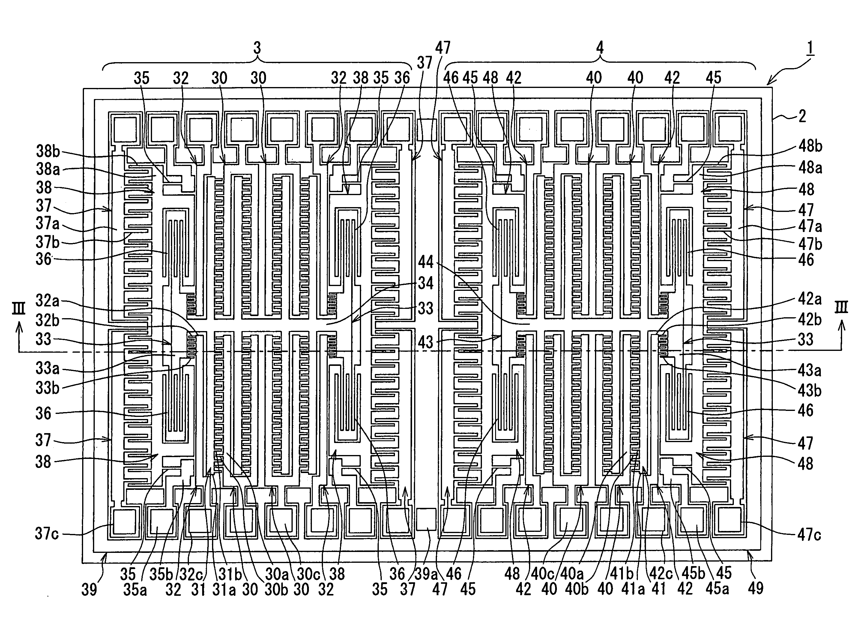
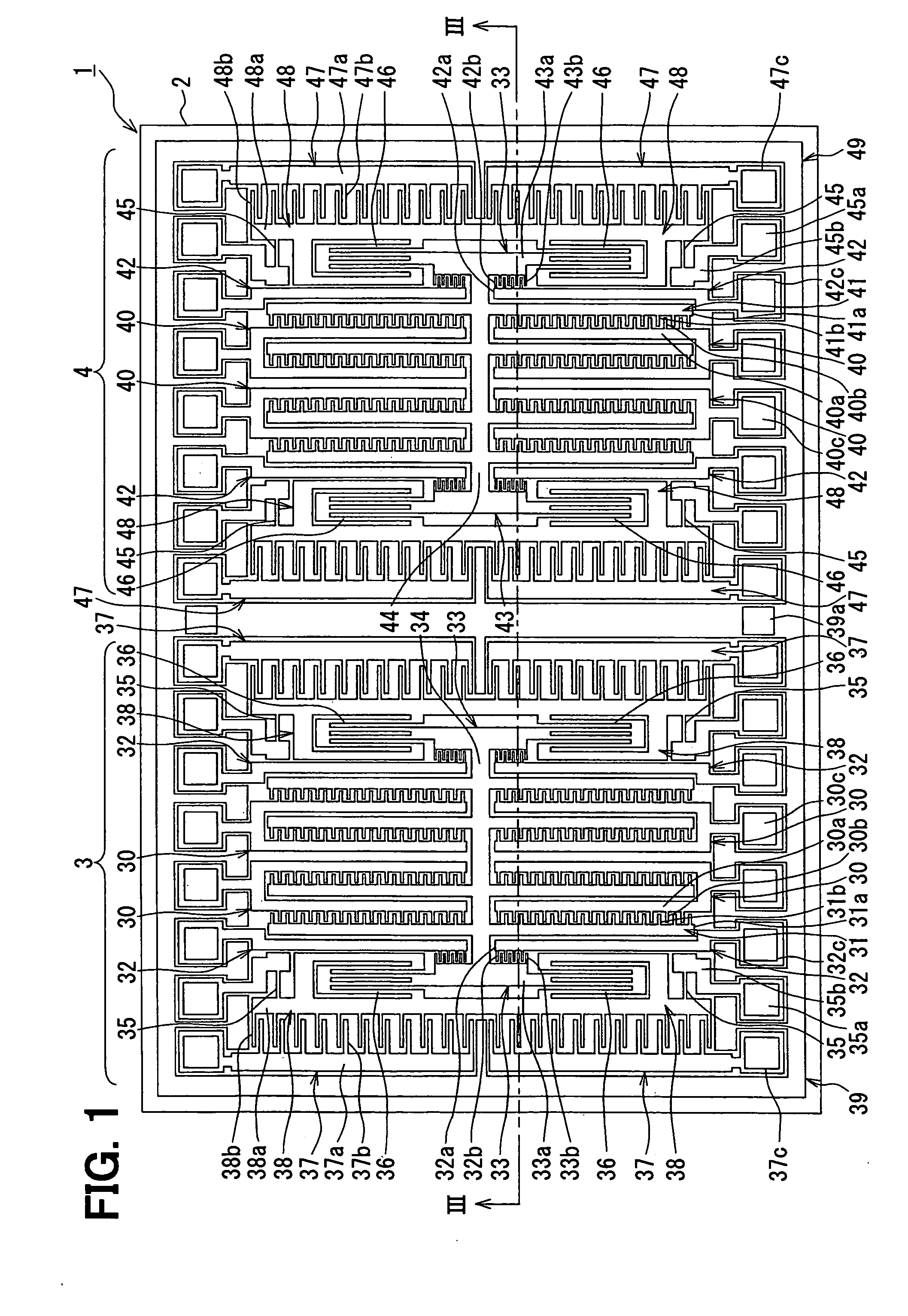
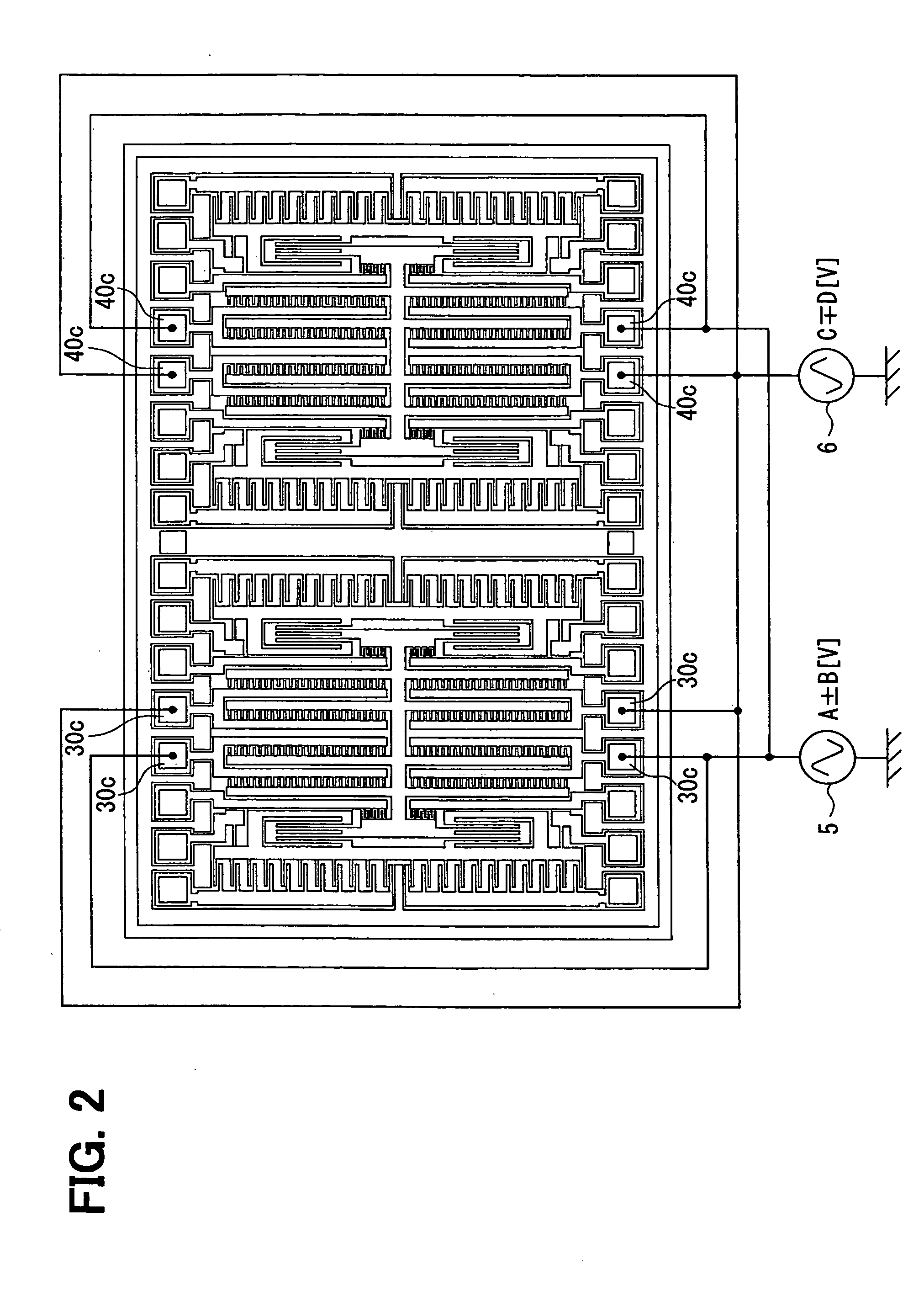
[0024]The inventors have studied, and it has been verified that a conventional method cannot attain a satisfactory canceling effect, but that it generates the output ascribable to the external acceleration. A cause is that a difference exists in drive resonance frequencies on account of the discrepancy of the product finishes of the left and right vibrators.

[0025]As shown in FIG. 7 by way of example, in a case where the difference exists in the respective drive resonance frequencies (i.e., frequencies at which amplitude ratios become peak points) of the left and right vibrators, the middle frequency of the respective drive resonance frequencies of the left and right vibrators is employed as a vibration frequency for actually driving the vibrators. This is because a frequency at which a value obtained by adding up the respective amplitude ratios of the left and right vibrators becomes the maximum is set as the vibration frequency. Here, VIIA in FIG. 7 represents an amplitude of a lef...


PUM


Abstract

An angular velocity sensor includes first and second vibrators having a movable portion with driving and detecting purpose movable electrodes and a fixed portion with first and second side driving and detecting purpose fixed electrodes. The driving voltages applied to the first side driving purpose fixed electrode in the first vibrator is a first driving voltage including direct and alternating voltages. The driving voltage applied to the second side driving purpose fixed electrode in the first vibrator is a second driving voltage including direct and alternating voltages. At least one of the direct voltages, one of the alternating voltages, or one of duty ratios of the first and second driving voltages is controlled so that the first vibrator vibrates opposite to the second vibrator.

Description

CROSS REFERENCE TO RELATED APPLICATIONS[0001]This application is based on Japanese Patent Applications No. 2006-52094 filed on Feb. 28, 2006, and No. 2006-260603 filed on Sep. 26, 2006, the disclosures of which are incorporated herein by reference.FIELD OF THE INVENTION[0002]The present invention relates to an angular velocity sensor and a method for manufacturing the same.BACKGROUND OF THE INVENTION[0003]In an angular velocity sensor, a movable electrode and a fixed electrode are disposed on a support substrate so as to oppose to each other, and an applied angular velocity is detected on the basis of the change of the distance between the movable electrode and the fixed electrode as is attendant upon the application of the angular velocity.[0004]In an angular velocity sensor such as a micro-gyro sensor of electrostatic drive / capacitance detection type, when an angular velocity is to be detected, a driving voltage is applied between a fixed electrode and a movable electrode for driv...

Claims


Application Information

Patent Timeline
Patent Type & Authority Applications(United States)
IPC IPC(8): G01P15/125G01C19/56G01C19/5726G01C19/574G01C19/5747
CPCG01C19/5719
Inventor KATSUMATA, TAKASHIITO, TAKESHIHIGUCHI, HIROFUMIOGINO, MITSUHITOMORISHIMA, TETSUYA
Owner DENSO CORP
Learn More