
Syringe assembly having disabling mechanism

Active Publication Date: 2007-08-16
BECTON DICKINSON & CO
View PDF3 Cites 30 Cited by
  • Summary
  • Abstract
  • Description
  • Claims
  • Application Information

AI Technical Summary

Benefits of technology

[0011] Another important advantage of the present invention is that in many embodiments, detents and discontinuities that function to achieve the desired result are annular, so that rotating the plunger rod with respect to the barrel will not distort, damage or defeat the locking element. A single use syringe will not be effective if it can be easily manipulated to overcome the locking mechanism for removing the components for re-assembly and reuse.
[0012] A further major advantage of the present invention is the single frangible zone in the stopper. In many designs there is no single point where a breaking feature may be added effectively and two or more components will have to be orchestrated to break under the same applied force to the plunger rod in an attempt to defeat the locking mechanism. In the present invention only one area needs to be weakened and it is centrally located safe from outside manipulation.
[0014] Other embodiments may include a plunger rod with two axially-spaced detents, and a post with three axially-spaced post detents so that the plunger rod can be moved distally two times before proximal motion of the plunger rod causes the locking element to engage the inside surface of the barrel.
[0015] The two axially-spaced detents of the plunger rod may include two axially-spaced steps, each having a blunt surface at its distal end extending inwardly from the interior surface of the plunger rod.
[0016] Some or all of the three axially-spaced post detents may include an incline surface extending proximally inwardly and a blunt surface at the distal end of each of the inclined surfaces extending radially inwardly.

Problems solved by technology

Although many of these devices work quite well, they do require the specific intent of the user followed by the actual act to destroy or render the syringe inoperable.
These devices are not effective with a user having the specific intent to re-use the hypodermic syringe.
The automatic function is much harder to provide because the means for rendering the syringe inoperable must not prevent its filling or use under normal conditions.

Method used


Image

  • Syringe assembly having disabling mechanism
  • Syringe assembly having disabling mechanism
  • Syringe assembly having disabling mechanism

Examples


Embodiment Construction

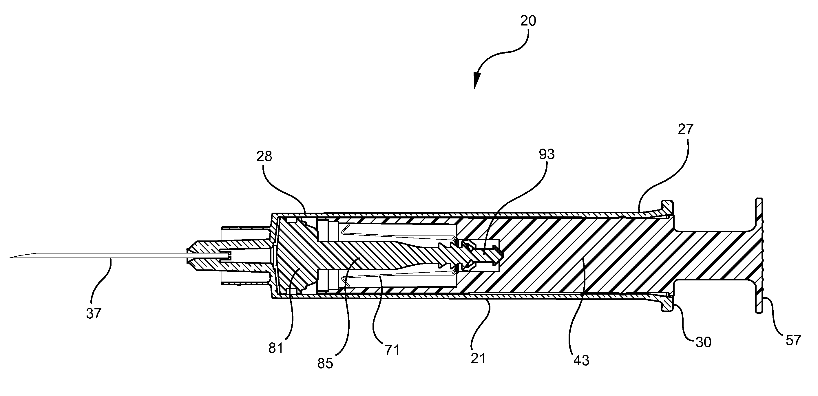
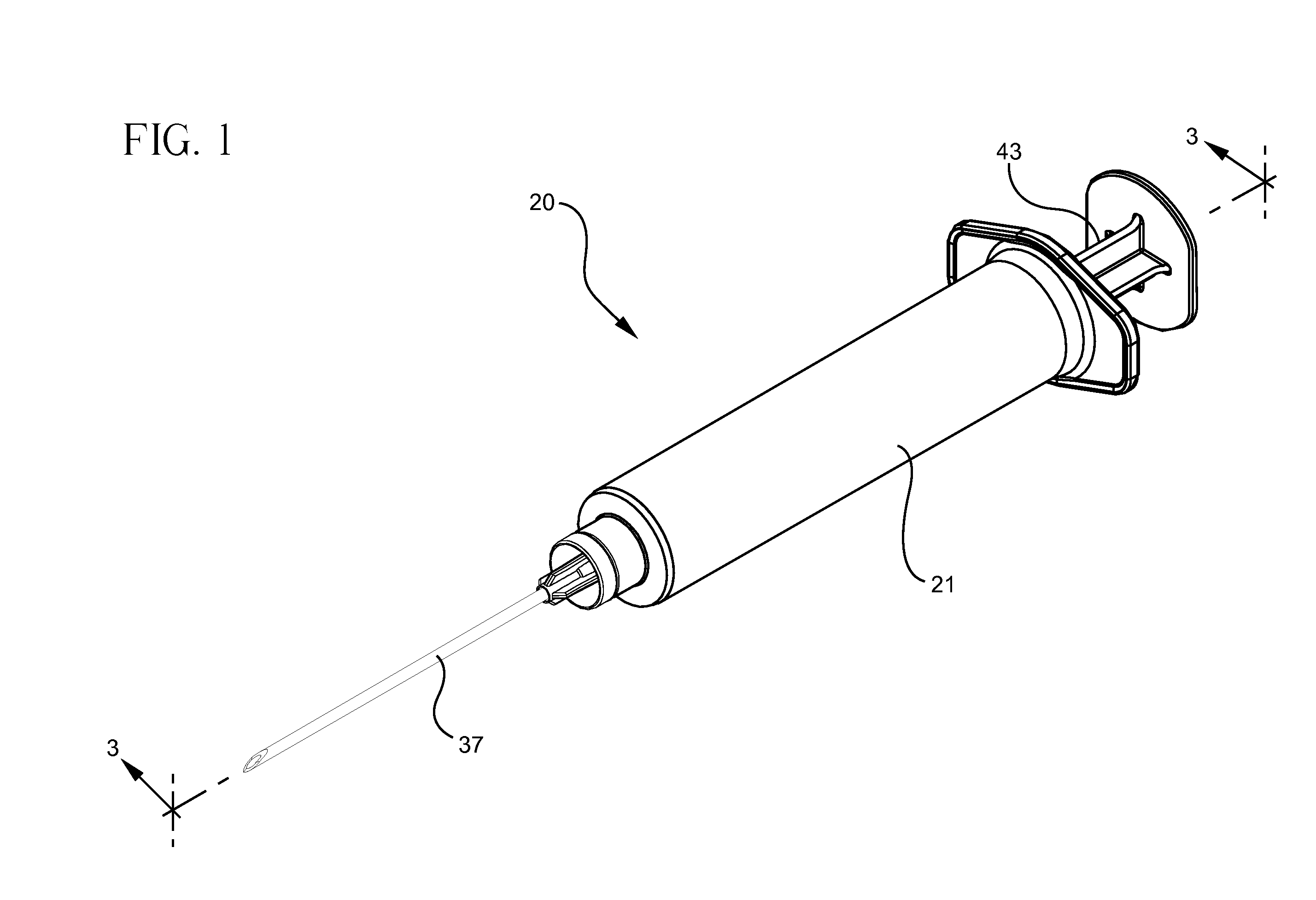
[0054] [Referring to FIGS. 1-18, a syringe assembly 20 having passive disabling features includes a barrel 21 and a plunger assembly 22. Barrel 21 includes a cylindrical side wall 23 having an inside surface 24 defining a chamber 25 for retaining fluid. The barrel further includes an open proximal end 27 and a distal end 28 including a distal wall 29 having a passageway 32 therethrough in fluid communication with the chamber. In this embodiment, the distal wall of the barrel includes an elongate tip 31 extending distally therefrom and having a passageway therethrough in fluid communication with the passageway in the distal wall. In this embodiment, barrel 21 also includes a needle cannula 37 having a proximal end 38, a distal end 39 and a lumen 40 therethrough. The proximal end of the needle cannula is attached to elongate tip 31 so that the lumen of the needle cannula is in fluid communication with passageway 32 in the barrel. A needle hub may also be attached to the proximal end o...


PUM


Abstract

A syringe assembly having passive disabling structure includes a barrel and a plunger rod assembly. The plunger rod assembly includes a plunger rod and a stopper connected by an indexing locking element. The number of strokes of the syringe plunger before the stopper is locked into the barrel rendering the syringe assembly unusable is determined by the number of detents on the plunger rod and stopper which engage the locking mechanism. Upon completion of the final delivery stroke, any attempt to withdraw the plunger rod from the barrel will cause the locking element to engage the barrel and trap the stopper in the barrel preventing further use of the syringe.

Description

FIELD OF THE INVENTION [0001] The present invention relates to syringe assemblies and particularly to syringe assemblies having an automatic disabling mechanism. BACKGROUND [0002] Throughout the world the multiple use of hypodermic syringe products which are intended for single-use only, is instrumental in drug abuse and in the transfer of contagious diseases. Intravenous drug users who routinely share and re-use syringes are a high-risk group with respect to the AIDS virus. Also, the effects of multiple use are a major concern in some countries where repeated use of syringe products during mass immunization programs may be responsible for the spread of many diseases. Re-use of single-use hypodermic syringe assemblies is also instrumental in the spread of drug abuse even in the absence of infection or disease. [0003] Many attempts have been made to remedy this problem. Most notable are early contributions which relied on a specific act to destroy the syringe after use either by usin...

Claims


Application Information

Patent Timeline
IPC IPC(8): A61M5/315
CPCA61M5/31515A61M5/5013A61M5/502A61M2005/5026A61M2005/5033A61M2005/5073A61M5/5066
Inventor BARERE, AARONODELL, ROBERT B. JR.
Owner BECTON DICKINSON & CO
Learn More