
Illumination device and display apparatus including the same

a technology of illumination device and display apparatus, which is applied in the direction of identification means, lighting and heating apparatus, instruments, etc., can solve the problems of uneven luminance and uneven luminance, and achieve the effect of reducing the degree of luminance unevenness (brightness) and high quality display

Inactive Publication Date: 2007-08-16
SHARP KK
View PDF38 Cites 0 Cited by
  • Summary
  • Abstract
  • Description
  • Claims
  • Application Information

AI Technical Summary

Benefits of technology

The present invention provides an illumination device for a display apparatus that can suppress unevenness of luminance and is suitable for use as a direct-type backlight. The device includes a plurality of rod-like light sources arranged parallel to each other, and a light scattering member located between adjacent light sources. The light scattering member is rod-like and acts as a pseudo light source, reducing the degree of unevenness of luminance in both the front and oblique directions. The invention also provides a display apparatus including the illumination device, which offers high quality display.

Problems solved by technology

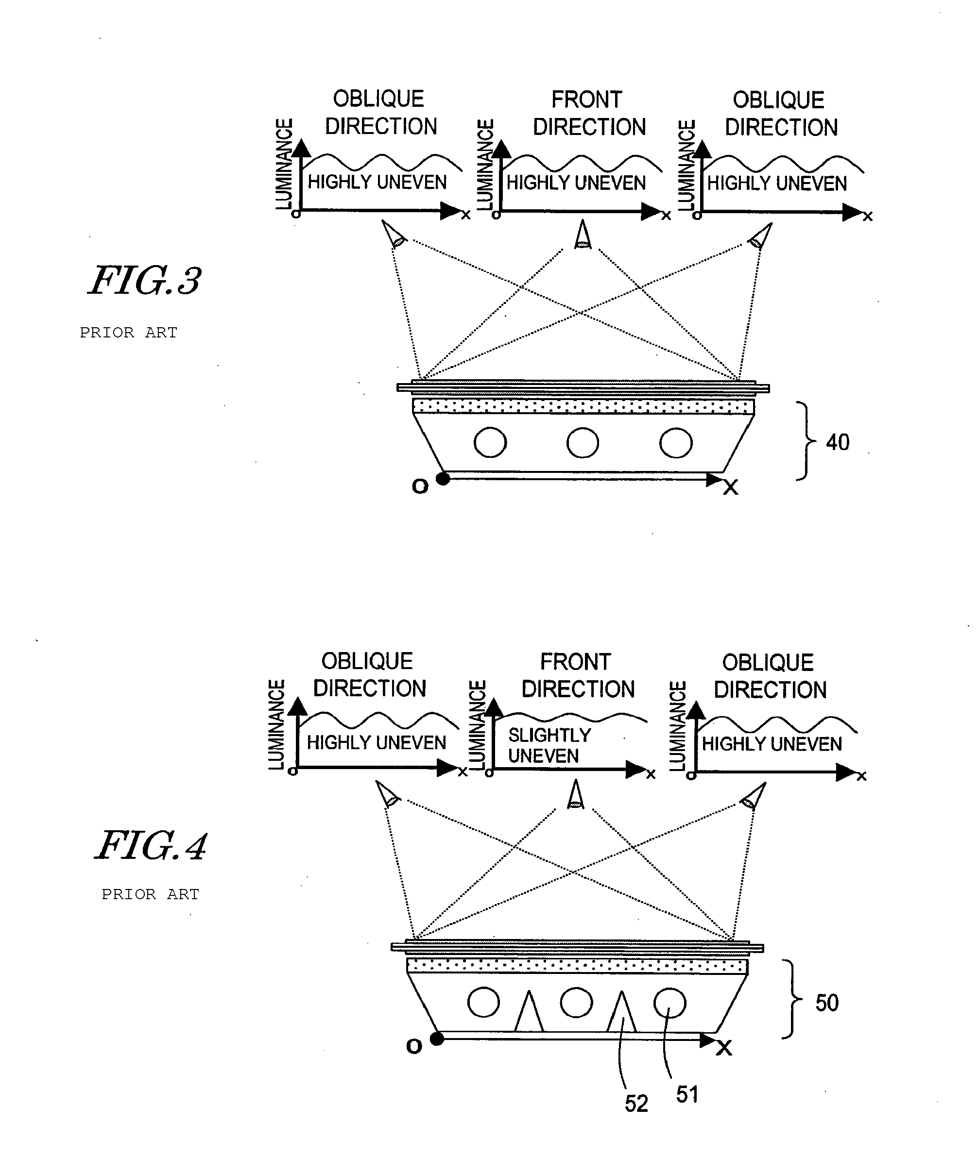
This results in uneven luminance.
However, these solutions also have the following problems.
As a result, it was found that the unevenness of luminance is not sufficiently suppressed either by the backlight disclosed in Japanese Laid-Open Patent Publication No. 2002-122863 or by the backlight disclosed in Japanese Laid-Open Patent Publication No. 2000-310776.

Method used


Image

  • Illumination device and display apparatus including the same
  • Illumination device and display apparatus including the same
  • Illumination device and display apparatus including the same

Examples


first preferred embodiment

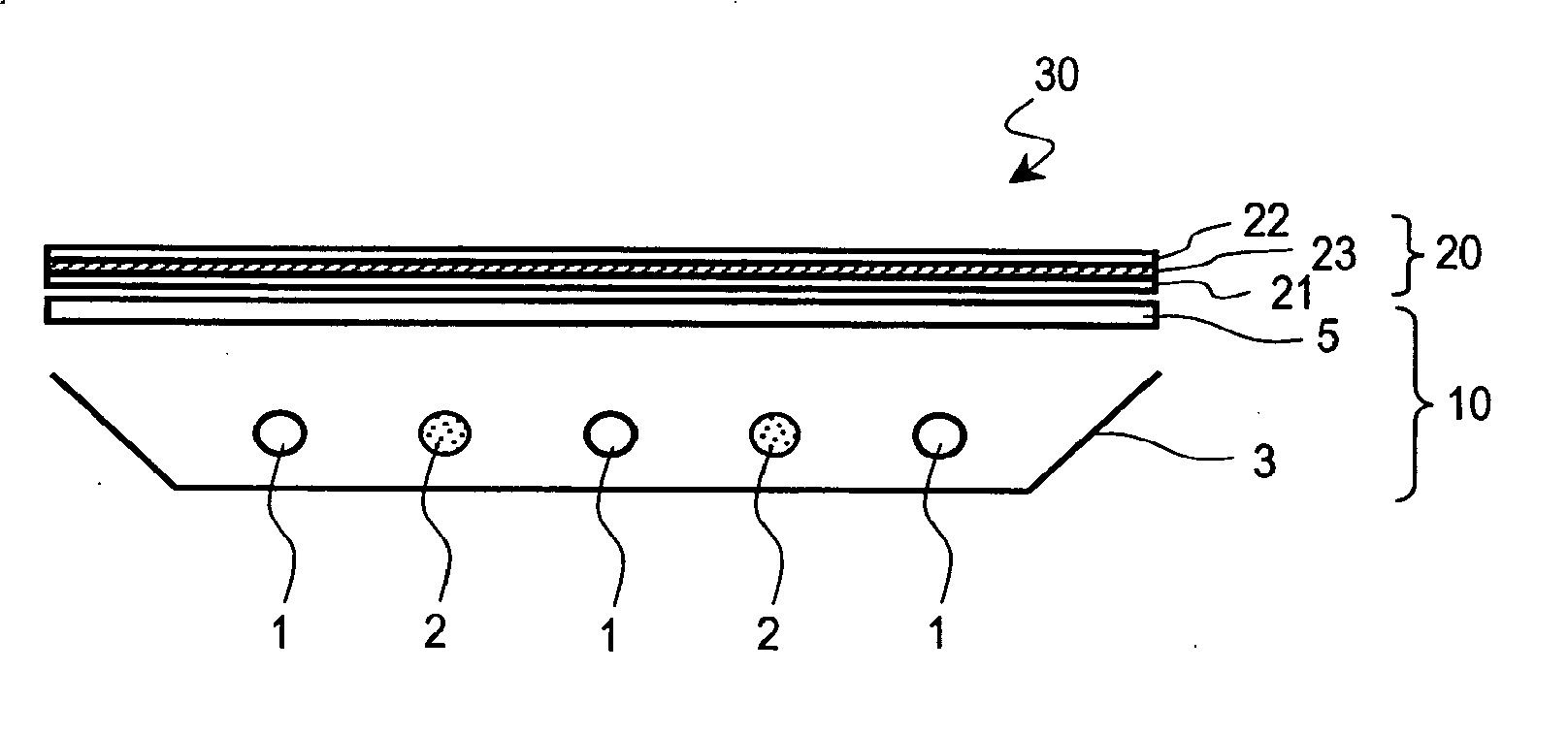
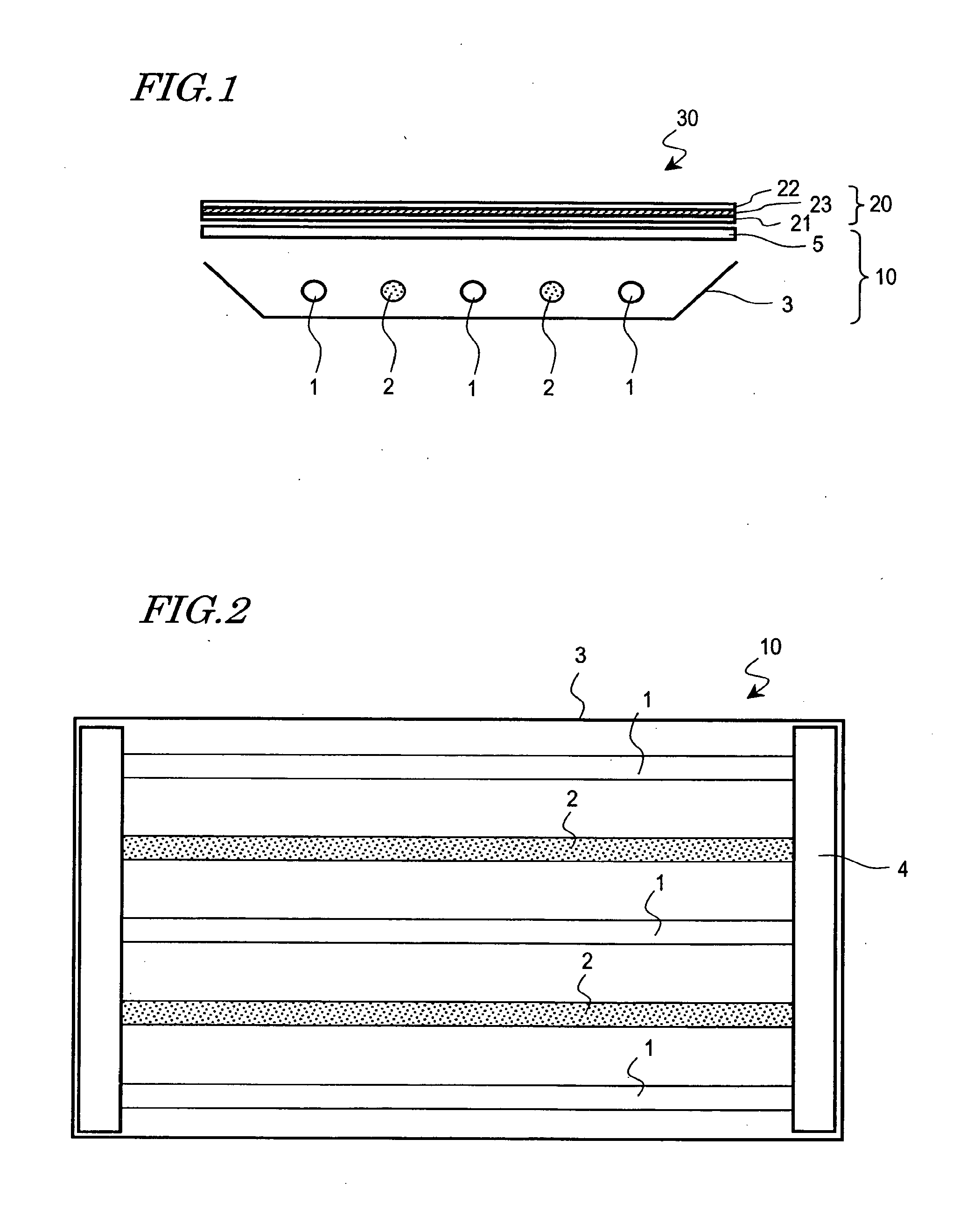
[0052] With reference to FIGS. 1 and 2, an illumination device 10 according to a first preferred embodiment of the present invention will be described. FIG. 1 is a cross-sectional view schematically illustrating a liquid crystal display apparatus 30 including the illumination device 10, and FIG. 2 is a plan view schematically illustrating the illumination device 10.

[0053] As shown in FIG. 1, the illumination device 10 is a so-called backlight which is located on a rear side (opposite from the observer) of a liquid crystal display panel 20 included in the liquid crystal display apparatus 30. The liquid crystal display panel 20 includes a pair of substrates (for example, glass substrates) 21 and 22 and a liquid crystal layer 23 provided between the pair of substrates 21 and 22. The liquid crystal display panel 20 displays images by modulating light from the illumination device 10. The liquid crystal display panel 20 has an area for displaying images in a transmission mode in each of ...

second preferred embodiment

[0070] With reference to FIG. 11, an illumination device 10′ according to a second preferred embodiment of the present invention will be described. The illumination device 10′ is also a backlight which is located on a rear side (opposite from the observer) of a liquid crystal display panel. Hereinafter, the illumination device 10′ will be described mainly regarding the points which are different from those of the illumination device 10 in the first preferred embodiment.

[0071] As shown in FIG. 11, the illumination device 10′ includes at least one U-shaped light source 1′ (FIG. 11 shows two U-shaped light sources 1′). Each U-shaped light source 1′ includes two rod-like sections (rod-like light emitting sections) 1a located parallel to each other and a bent section 1b for connecting the two rod-like sections 1a. The U-shaped light source 1′ in this preferred embodiment is a cold cathode fluorescent tube.

[0072] The illumination device 10′ further includes a light scattering member 2 f...


PUM

PropertyMeasurementUnit
light scatteringaaaaaaaaaa
outer diameteraaaaaaaaaa
shapeaaaaaaaaaa

Abstract

An illumination device for a display apparatus provided on a rear side of a display panel of the display apparatus includes a plurality of rod-like light sources arranged substantially parallel to each other; and a light scattering member for scattering light, the light scattering member being provided between two adjacent rod-like light sources among the plurality of rod-like light sources.

Description

BACKGROUND OF THE INVENTION [0001] 1. Field of the Invention [0002] The present invention relates to an illumination device and a display apparatus including the same; and specifically to an illumination device provided on a rear side of a display panel and usable as a backlight of a display apparatus, and a display apparatus including such an illumination device. [0003] 2. Description of the Related Art [0004] Liquid crystal display apparatuses are widely used for electronic office equipment, vehicle-mountable TVs, monitors of video cameras and the like owing to the features of being light weight, thin and low in power consumption. Unlike self-luminous display apparatuses including CRTs (cathode-ray tubes), PDPs (plasma display panels) and EL (electroluminescence) units, liquid crystal display apparatuses use a liquid crystal display device which is not self-luminous. Therefore, transmissive liquid crystal display apparatuses include a planar illumination device referred to as a ba...

Claims


Application Information

Patent Timeline
Patent Type & Authority Applications(United States)
IPC IPC(8): F21S4/00F21V5/00F21V1/00F21S2/00F21S8/04F21V7/04F21Y103/00G01D11/28G02F1/1335G02F1/13357G09F9/00
CPCG02F1/133604G02F1/133611G02F1/133606G02F1/1335
Inventor TAKATA, YOSHIKI
Owner SHARP KK
Learn More