
Collateral pathway treatment using agent entrained by aspiration flow current

a technology of aspiration flow current and agent, which is applied in the field of performing catheter-based diagnostic or therapeutic procedures within the lung, can solve the problems of affecting lung function, affecting lung function, and affecting lung function,

Inactive Publication Date: 2007-08-16
PULMONX
View PDF7 Cites 44 Cited by
  • Summary
  • Abstract
  • Description
  • Claims
  • Application Information

AI Technical Summary

Problems solved by technology

In some disease states, such interconnections at the lung lobule level and / or connections through incomplete fissures can become more pronounced rendering certain treatments problematic.
However, if collateral interconnections exist, LVR can be hampered since the collapsed region can re-inflate through any collateral connection.
These treatments however are destructive and have not yet achieved good safe results and are considered undesirable.
Unfortunately, this technique has a significant disadvantage in that the targeting of the agent is poorly controlled with the methods they describe.
An additional disadvantage of this technique is that the user must perform lung volume reduction on the patient by implanting bronchial valves or occluders in order to diagnose whether or not the patient possess collateral channels.
This is a very inconvenient treatment protocol.

Method used


Image

  • Collateral pathway treatment using agent entrained by aspiration flow current
  • Collateral pathway treatment using agent entrained by aspiration flow current
  • Collateral pathway treatment using agent entrained by aspiration flow current

Examples


first embodiment

[0020] Referring to FIGS. 3A-3D, the invention is described. The lung area targeted for therapy is first isolated with a balloon catheter 10 (FIG. 3A), henceforth referred to as the aspiration catheter, which is inserted through the mouth and the main bronchus B and into the tracheobronchial tree, optionally using a bronchoscope or other delivery tube or sheath (not shown). The target lung area can be in the lobar bronchus, the segmental bronchus or even deeper into the bronchial tree, depending on what the needs of the therapy are and where the targeted lung bronchopulmonary compartment, henceforth referred to as the target lung region (TLR), is located. Isolation is created usually by inflating a balloon or cuff 12 at the tip of the catheter which seals the annular space between the catheter and the bronchus wall. A lumen extends the length of the catheter providing access to the targeted lung region (TLR). The proximal end of the catheter 10 outside the patient's body is coupled ...

second embodiment

[0030] In the present invention, a method and devices are disclosed in which the agent that is delivered is designed to have a state change or undergo chemical alteration after being deposited in the collateral pathway. The state change allows the agent to be delivered in a highly particalized small state in order to maximize time-of-flight and penetration into the collateral pathways. Once deposited, the agent can change to a less particalized state with sufficient persistence to stay at the site of deposition. For example, typical sizes of the particles in the particulate state can have molecular weights of 100-500 Daltons versus molecular weights of 100-1,000 KDa in an agglomerated or coalesced state. The larger size would immoblize the agent onto the host tissue to resistant migration. The particles in the delivered state may also be hydrophobic or lubricious or very light in viscosity and generally highly un-reactive with like particles in order to maximize penetration into the...


PUM


Abstract

A method and system for increasing the flow resistance of pathways in the lung by employing aspiration to establish an artificial convective flow current between compartments in the lung in order to entrain and deliver a clogging agent preferentially to the pathways. This treatment is performed after an area has been properly diagnosed for treatment.

Description

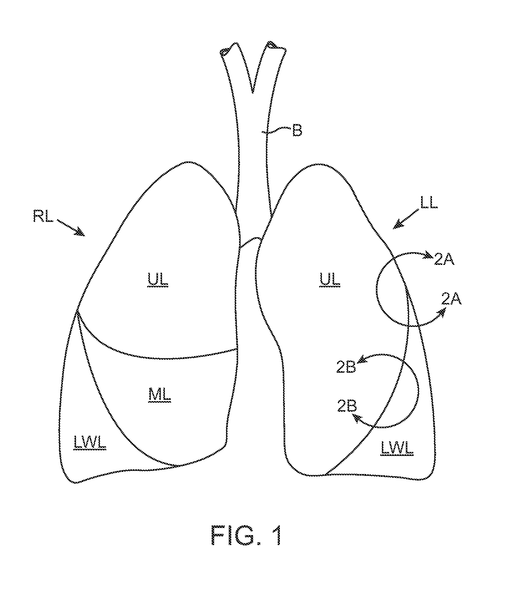
CROSS-REFERENCES TO RELATED APPLICATIONS [0001] The present application claims the benefit of provisional U.S. Application No. 60 / 756,732 (Attorney Docket No. 017534-003300US), filed Jan. 6, 2006, the full disclosure of which is incorporated herein by reference.BACKGROUND OF THE INVENTION [0002] The subject invention relates to performing catheter-based diagnostic or therapeutic procedures within the lung. In particular, the invention relates to closing or partially closing intercommunicating channels within the lung in order to prevent a target lung compartment from receiving collateral ventilation through such intercommunicating secondary channels. [0003] The lung consists of a left lung and right lung having two and three lobes respectively (FIG. 1). Air is delivered into and out of the lobes of the lungs through a bronchial system comprising tubular airways starting with the trachea which divides and subdivides until the airways reach the periphery of the lobes terminating in lo...

Claims


Application Information

Patent Timeline
IPC IPC(8): A61M37/00A61M1/00A62B9/06A61M16/00
CPCA61B2017/00809A61M2210/1039A61M2025/1052A61M25/10
Inventor WONDKA, ANTHONYSOLTESZ, PETER
Owner PULMONX
Learn More