
Process and system for improving combustion and exhaust aftertreatment of motor vehicle engines

a technology for exhaust aftertreatment and motor vehicles, which is applied in the direction of combustion-air/fuel-air treatment, machines/engines, electric control, etc., can solve the problems of nitrogen oxide compound detriment, fuel-air mixture may produce, and the approach is best at medium engine load, and not very well at high load or very low load

Inactive Publication Date: 2007-08-09
DELPHI TECH INC
View PDF13 Cites 13 Cited by
  • Summary
  • Abstract
  • Description
  • Claims
  • Application Information

AI Technical Summary

Benefits of technology

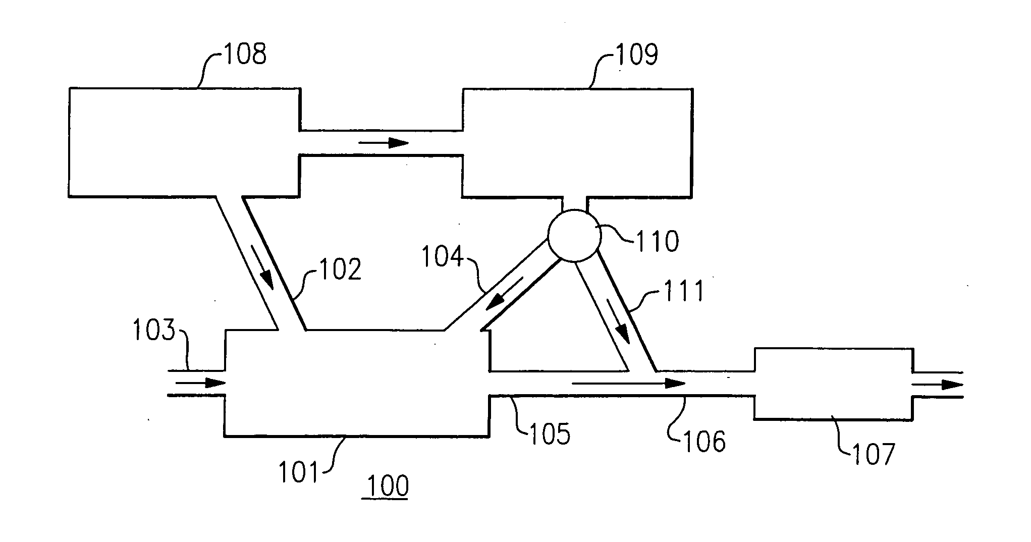
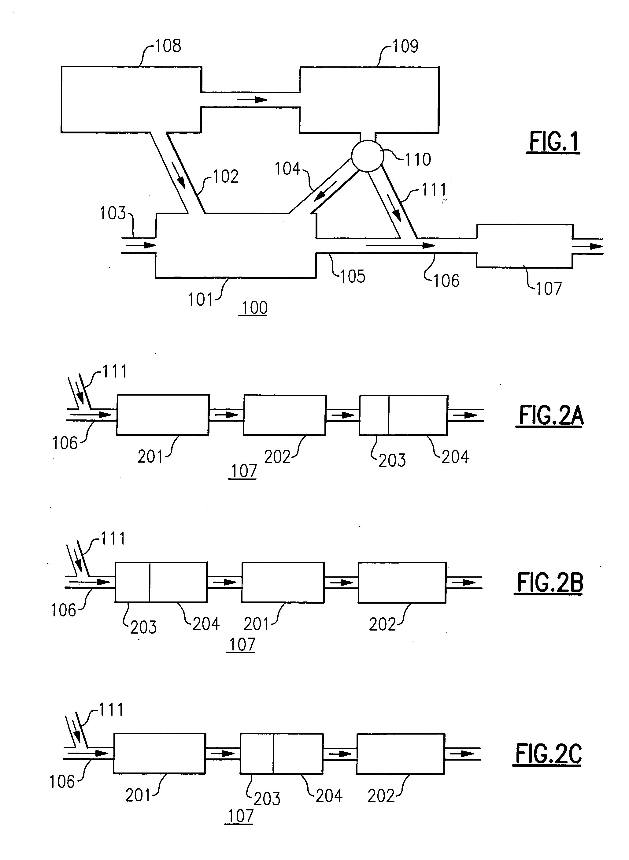
The present invention is about a system for improving fuel combustion and exhaust aftertreatment in a diesel engine. It includes a fuel system with a liquid fuel intake, air intake, and a fuel reformer that produces a hydrogen-rich reformate. The exhaust conduit has a reformate conduit with exhaust aftertreatment components. The system can supply different mixtures of liquid diesel fuel and reformate to the engine depending on the engine load. This system improves fuel combustion and exhaust aftertreatment under different engine load conditions.

Problems solved by technology

Further, the very high temperatures produced by the burning of the hydrocarbon fuels with air results in the detrimental formation of nitrogen oxide compounds (NOx).
This approach works best at medium engine loads but not very well at high loads or very low loads.
For high loads, detonation of the fuel-air mixture may produce high combustion rates and noise.
For very low loads, the mixture is very lean and ignition may become unstable, with increased occurrence of misfire cycles.
The main technical challenges are control of combustion initiation, timing and rate to achieve effective premixed combustion over an extended range of engine load.
However, this period of fuel-rich combustion may also result in a significant fuel penalty.

Method used


Image

  • Process and system for improving combustion and exhaust aftertreatment of motor vehicle engines
  • Process and system for improving combustion and exhaust aftertreatment of motor vehicle engines

Examples


Embodiment Construction

[0013] In a diesel engine capable of operating in a premixed combustion mode, conventional diesel combustion can be advantageously employed at high loads and at very low loads, premixed combustion being most suitable under conditions of low and medium loads. Exhaust aftertreatment components included in the exhaust conduit are used to control NOx and particulate emissions, especially for conventional diesel combustion at high and very low engine loads.

[0014] The reformate produced by an on-board catalytic fuel reformer in the engine system of the present invention can be combined with the liquid diesel fuel to enable a wide range of cetane numbers to be achieved, which allows for controlled variation of the timing and rate of premixed diesel combustion.

[0015] The diesel combustion engine system of the present invention provides for good combustion performance at low, medium, and high engine loads. For a given engine speed, low engine load is considered to lie at or below about one...


PUM


Abstract

A diesel combustion engine system providing improved fuel combustion and exhaust aftertreatment includes: a diesel combustion engine having a liquid fuel intake, an air intake, a reformate intake, and an exhaust outlet; a liquid diesel fuel source in fluid communication with the liquid fuel intake and an on-board catalytic partial oxidation fuel reformer that receives a supply of hydrogen-containing liquid diesel fuel and a supply of air and produces therefrom a hydrogen-rich reformate. An exhaust conduit in fluid communication with the exhaust outlet and the reformer includes a reformate conduit upstream from exhaust aftertreatment components. The system provides for supplying: under conditions of low engine load, reformate or a combination of liquid diesel fuel and reformate to the engine; under conditions of medium engine load, a combination of liquid diesel fuel and reformate to the engine; and, under conditions of high engine load, liquid diesel fuel only to the engine and reformate only to the exhaust conduit.

Description

TECHNICAL FIELD [0001] The present invention relates to the combustion of hydrocarbon fuels and the generation of exhaust in internal combustion engines and, more particularly, to a process and system for improving fuel combustion and exhaust aftertreatment in a diesel engine. BACKGROUND OF THE INVENTION [0002] Internal combustion engines, including diesel engines, operate by the controlled combustion of hydrocarbon fuels and produce exhaust gases containing complete combustion products such as carbon dioxide (CO2) and water (H2O), and incomplete combustion products such as carbon monoxide (CO) and unburned hydrocarbons (HC). Further, the very high temperatures produced by the burning of the hydrocarbon fuels with air results in the detrimental formation of nitrogen oxide compounds (NOx). Certain undesirable components of the exhaust, including CO, HC, NOx, and soot particulates must be controlled to meet government emissions regulations. [0003] Diesel engines are characterized by h...

Claims


Application Information

Patent Timeline
Patent Type & Authority Applications(United States)
IPC IPC(8): F01N3/00F01N3/10
CPCF01N3/021F01N13/0093F01N3/035F01N3/0842F01N3/103F01N3/206F01N2240/30F02B3/06F02D19/081F02D41/0025F02D41/0235F02M25/10F02M27/02Y02T10/121Y02T10/36F02D19/0644F02D19/0671F01N13/009F01N13/0097F01N3/0253Y02T10/12Y02T10/30Y02A50/20
Inventor SELLNAU, MARK C.QUADER, ATHERKIRWAN, JOHN E.
Owner DELPHI TECH INC
Learn More