
Self contained bench top enclosure temperature control system

Inactive Publication Date: 2007-08-02
POLYMER INNOVATIONS
View PDF3 Cites 4 Cited by
  • Summary
  • Abstract
  • Description
  • Claims
  • Application Information

AI Technical Summary

Benefits of technology

[0007] In one mode of operation, the heater adds heat to the target until the input temperature is less than the set point temperature. Then the heater shuts-off when the temperature of the target reaches or exceeds the first set point temperature. In another mode of operation, the heater not only shuts-off when the temperature of the target reaches or exceeds the first set point temperature but also the fan comes on and blows cold ambient air to the target when the input temperature or the temperature of the target exceeds the second set point temperature which is normally set

Problems solved by technology

The visual observation of the chemical reaction or polymerization may not be possible because the reaction flask or resin kettle is normally dipped inside the well of the heating mantel which blocks the vision.
The other drawbac

Method used


Image

  • Self contained bench top enclosure temperature control system
  • Self contained bench top enclosure temperature control system

Examples


Example

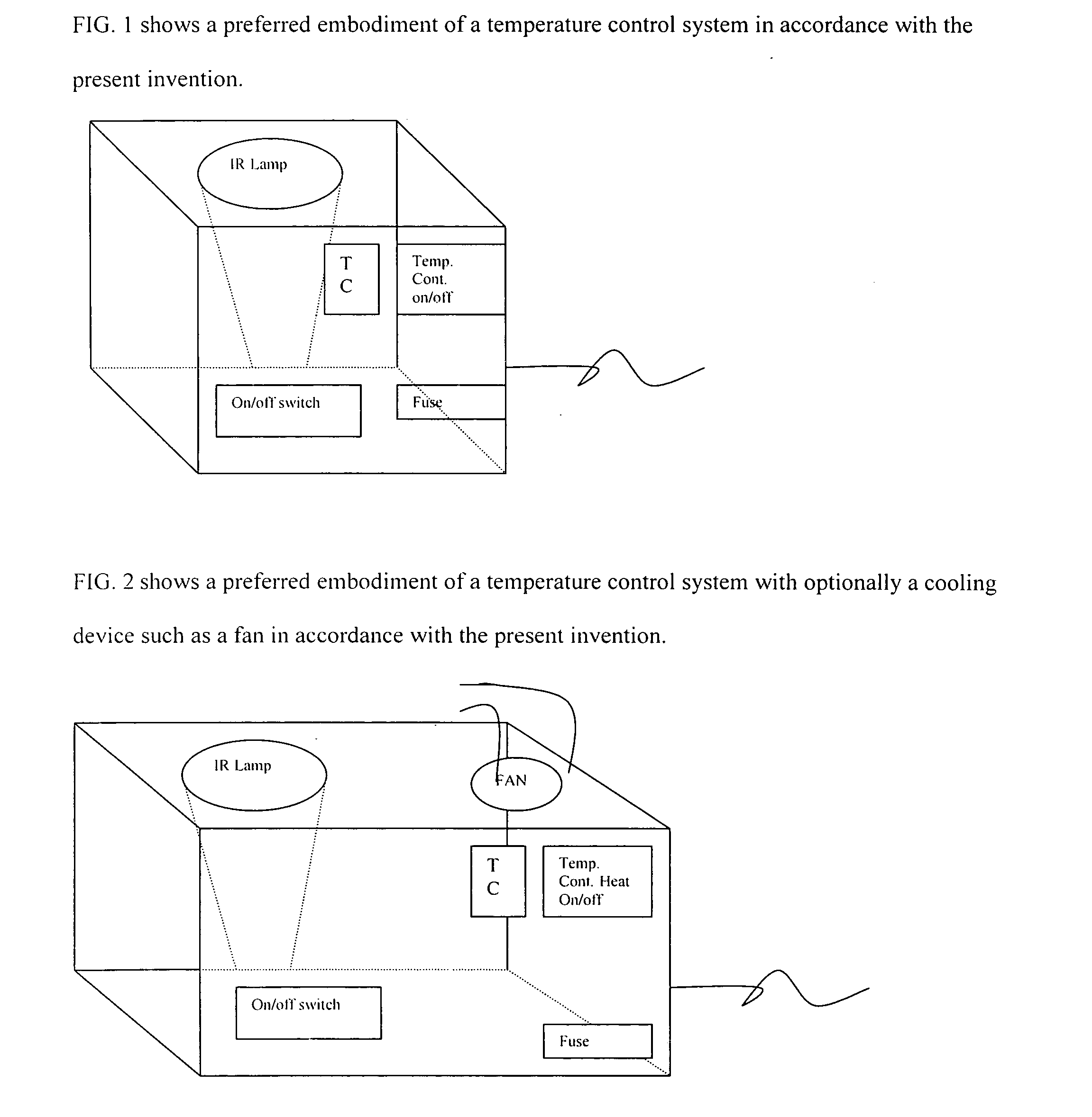
[0009] With reference now to FIG. 1, the details of a preferred embodiment of the present invention will be described. This FIG. 1 embodiment shows a self contained box that contains a temperature controller and a heating device such as an infrared heat producing electrical bulb. The box also includes an on / off switch, a socket for a thermocouple (TC), and fuse. The box may also contain alarm unit and other required electronics and wiring which are not shown. The power supply cord is also attached as shown.

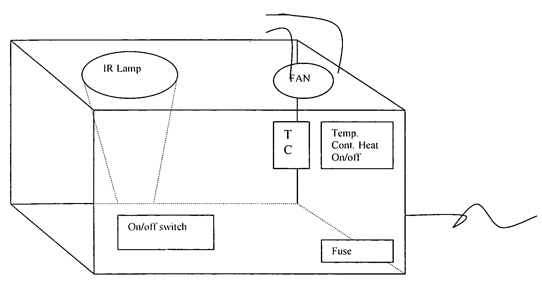
[0010] With reference now to FIG. 2, the details of a preferred embodiment of the present invention will be described. This FIG. 2 embodiment shows a self contained box that contains a temperature controller and a heating device such as an infrared heat producing electrical bulb and a cooling device such as a fan. The box also includes an on / off switch, a socket for a thermocouple (TC), and fuse. The box may also contain alarm unit and other required electronics and wiring which ...


PUM


Abstract

A self contained bench top enclosure temperature control system that includes a heating device which is an infrared heat producing electrical bulb and a temperature controller and with or without a cooling device which is a fan designed to blow ambient air has been described.

Description

BACKGROUND OF THE INVENTION [0001] The present invention relates to temperature control systems for controlling the temperature of a target such as a chemical reaction, polymerization, liquid, fluid, solvent-solute system or any other matter of which the temperature needs to be controlled. More particularly, the present invention relates to a self contained bench top enclosure temperature control system comprises a heating device which is an infrared heat producing electrical bulb; a cooling device which is a fan designed to blow ambient air; a temperature controller having input terminals that receives said input temperature signal from the target and having an electronic circuit that generates either heater control signal thus directs said heater or infrared heat producing bulb to glow to add heat to the target until it reaches a set point or generates cooler control signal directs said fan to blow cold ambient air to the target when said temperature of the target exceeds a set po...

Claims


Application Information

Patent Timeline
IPC IPC(8): G05D23/00
CPCB01L7/00B01L2200/147B01L2300/1872B01L2300/1844B01L2300/0627
Inventor MISHRA, MUNMAYA KUMAR
Owner POLYMER INNOVATIONS
Learn More