
Methods for detecting osteolytic conditions in the body

Active Publication Date: 2007-08-02
WARSAW ORTHOPEDIC INC
View PDF99 Cites 41 Cited by
  • Summary
  • Abstract
  • Description
  • Claims
  • Application Information

AI Technical Summary

Benefits of technology

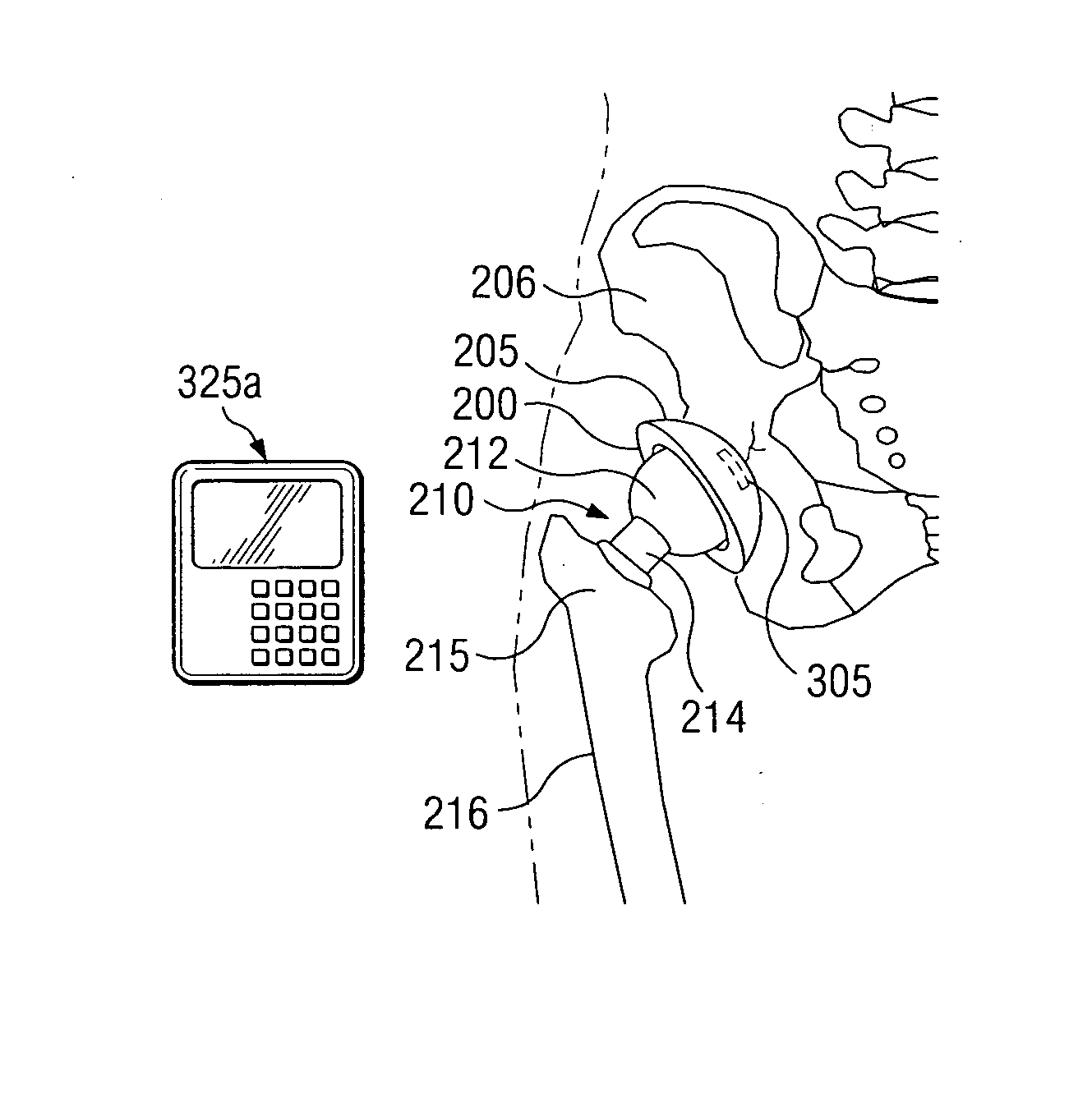
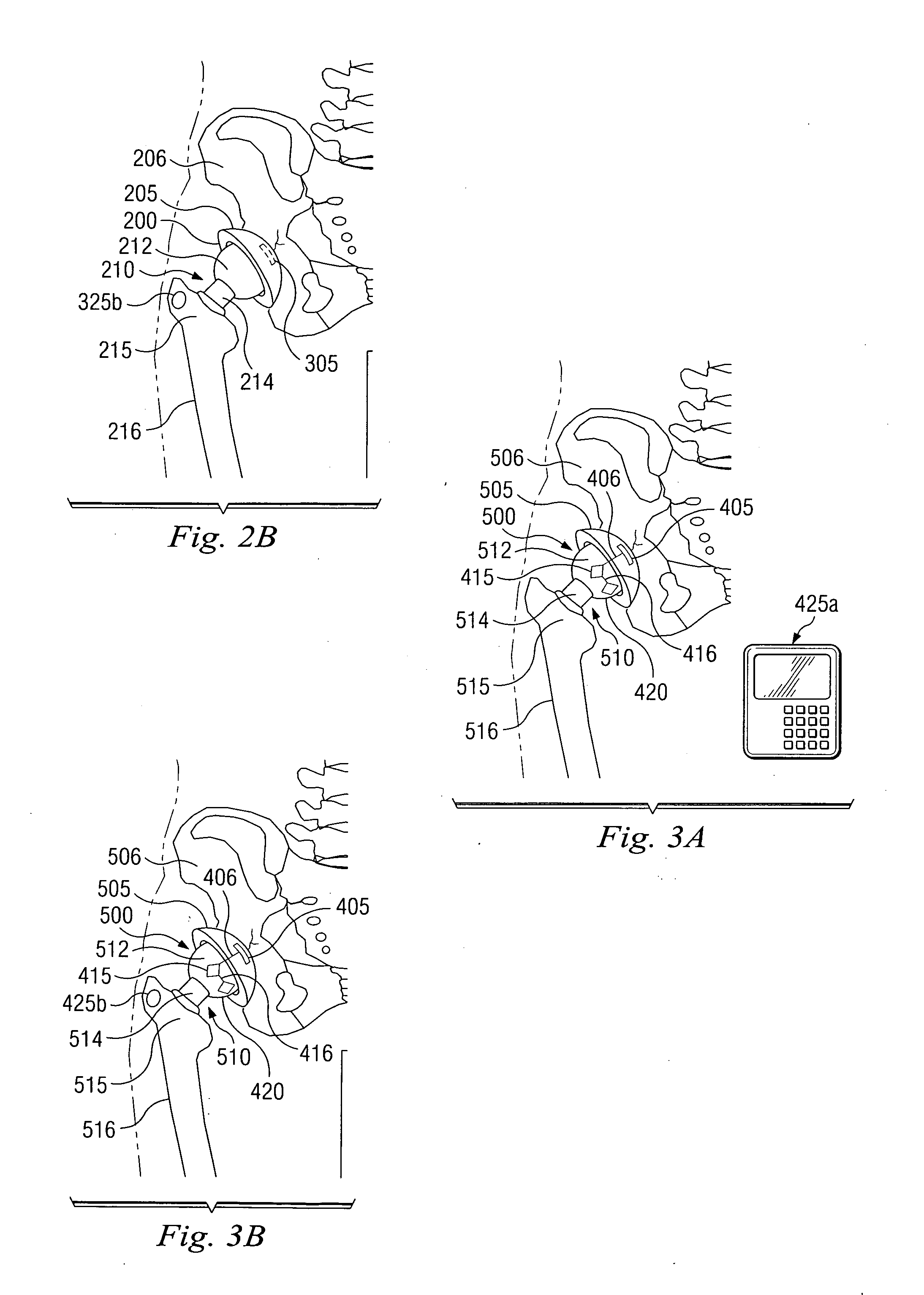
[0010] The disclosure can be more clearly understood by reference to the following drawings, which illust

Problems solved by technology

It has been determined that the debris created by the wearing of a prosthetic implant may contribute to local bone destruction and osteolysis.
Unfortunately, it is difficult to detect the synthetic debris particles and / or their concentration in the body.
Loosening of the boney attachment to the implant or the cement agent and / or material debris from the wear of the prosthetic itself can cause additional problems for the patient.

Method used


Image

  • Methods for detecting osteolytic conditions in the body
  • Methods for detecting osteolytic conditions in the body
  • Methods for detecting osteolytic conditions in the body

Examples


Embodiment Construction

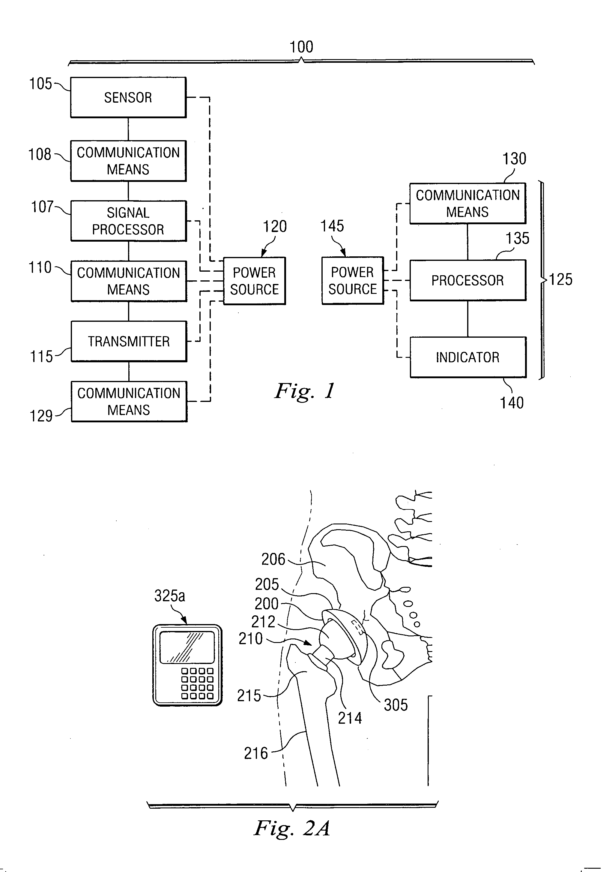
[0024] Referring now to FIG. 1, one embodiment of a system for detecting a condition in the body according to the present disclosure is illustrated.

[0025] According to the embodiment illustrated in FIG. 1, a detection system 100 comprises a sensor 105, a signal processor 107, and a transmitter 115. The sensor 105 and the signal processor 107 are communicatively coupled by communication means 108, and the signal processor 107 and the transmitter 115 are communicatively coupled by communication means 110. Communication means 108 and 110 can be wired or wireless, as will be discussed further herein. In certain embodiments, signal processor 107 could contain a memory unit, or could be communicatively coupled to a memory unit. As will be discussed further herein, a memory unit would store data received from the signal processor.

[0026] For ease of reference, the sensor 105, signal processor 107, and transmitter 115, are illustrated separately in FIG. 1, and are discussed as separate uni...


PUM


Abstract

Methods and systems for detecting a biological response indicative of osteolysis or osteolytic pre-conditions in bone.

Description

BACKGROUND OF THE INVENTION [0001] The present disclosure relates generally to methods and devices for detecting osteolytic conditions or pre-conditions in the body. [0002] Human joints, such as the knee, shoulder, elbow, hip, and vertebral joints can be replaced by prostheses or implants. Such prostheses can be fixed to surrounding bone by bone ingrowth into the implant or external features that extend into the bone. Additionally, implants can be fixed in the bone with a cement agent, such as polymethylmethacrylate. [0003] It has been determined that the debris created by the wearing of a prosthetic implant may contribute to local bone destruction and osteolysis. Unfortunately, it is difficult to detect the synthetic debris particles and / or their concentration in the body. [0004] Loosening of the boney attachment to the implant or the cement agent and / or material debris from the wear of the prosthetic itself can cause additional problems for the patient. Thus, there remains a need ...

Claims


Application Information

Patent Timeline
IPC IPC(8): A61B5/117A61B5/103A61B5/00A61N1/00A61F2/32A61B5/05
CPCA61B5/0031A61F2250/0002A61B5/076A61B5/14539A61B5/4528A61B5/6882A61B17/68A61B17/86A61F2/2803A61F2/32A61F2/34A61F2/36A61F2/38A61F2/3804A61F2/40A61F2/4202A61F2/4261A61F2/44A61F2/4609A61F2002/30405A61F2002/30448A61F2002/30449A61F2002/3067A61F2002/30794A61F2002/3403A61F2002/3404A61F2002/3412A61F2002/3414A61F2002/3429A61F2002/3611A61F2002/3625A61F2002/48A61F2002/488A61F2220/0025A61F2220/005A61B5/01A61F2002/3079A61F2/488A61F2/48
Inventor NYCZ, JEFFREY H.DRAPEAU, SUSAN J.DONOFRIO, WILLIAM T.
Owner WARSAW ORTHOPEDIC INC
Learn More