
Tube and tube pump

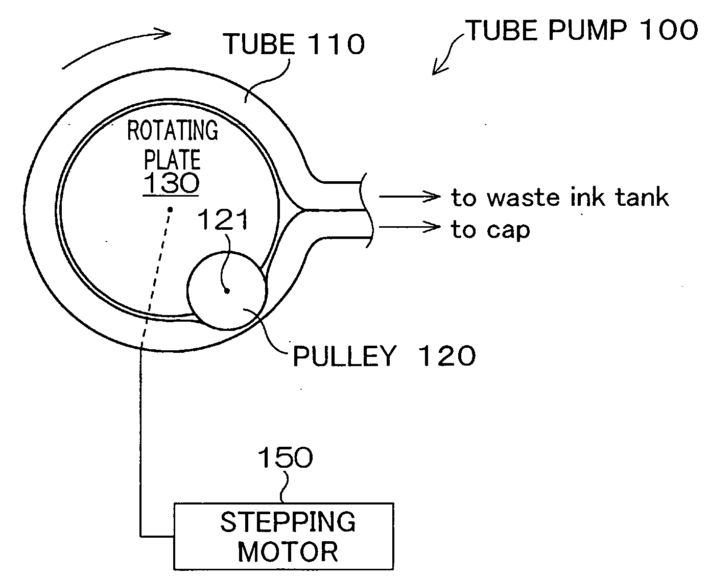
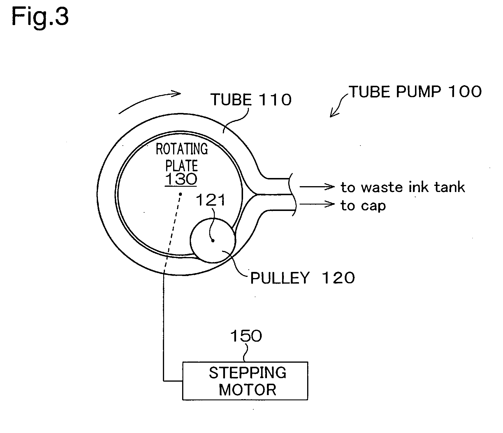
a tube pump and tube tube technology, applied in the direction of pump control, pumping pump, positive displacement liquid engine, etc., can solve the problems of inability to create adequate negative pressure during subsequent recovery, inability to smoothly eject the needle, and high torque, so as to achieve the effect of adequate fluid pumping force and excessively high compressing for

Inactive Publication Date: 2007-08-02
SEIKO EPSON CORP
View PDF10 Cites 0 Cited by
  • Summary
  • Abstract
  • Description
  • Claims
  • Application Information

AI Technical Summary

Benefits of technology

[0008]An object of the present invention is to provide technology whereby an adequate level of fluid pumping force can be created, without the need for an excessively high level of compressing force.
[0010]According to this design, since the tube receives compressing force via the portion of the wall having the greater second thickness, the portion of the wall having the smaller first thickness will readily deform thereby, so that the hollow flow passage is compressed to a sufficient extent. Consequently, an adequate level of fluid pumping force can be created without an excessively high level of compressing force.
[0014]According to this design, when compressing force acts on the wall portion, the deformation assisting wall portion will reliably undergo deformation, compressing the hollow portion and readily assuming an occluded state, thereby eliminating the need for an excessively high level of compressing force.
[0016]According to this design, since the curvature of the outside of the wall portion is smaller than the curvature of the hollow portion, the outside of the wall portion will deform, become smaller in curvature, and assume a flatter state due to the compressing force (which is the contact force of the compressing mechanism); and with further compression, the corner portions directly receive the compressing force of the compressing mechanism. Consequently, since the compressing force acts on the contact resistant portions via the corner portions, the contact resistant portions reliably come into mutual contact, and a sufficiently compressed (occluded) state of the hollow portion can be produced without an excessively high level of compressing force.

Problems solved by technology

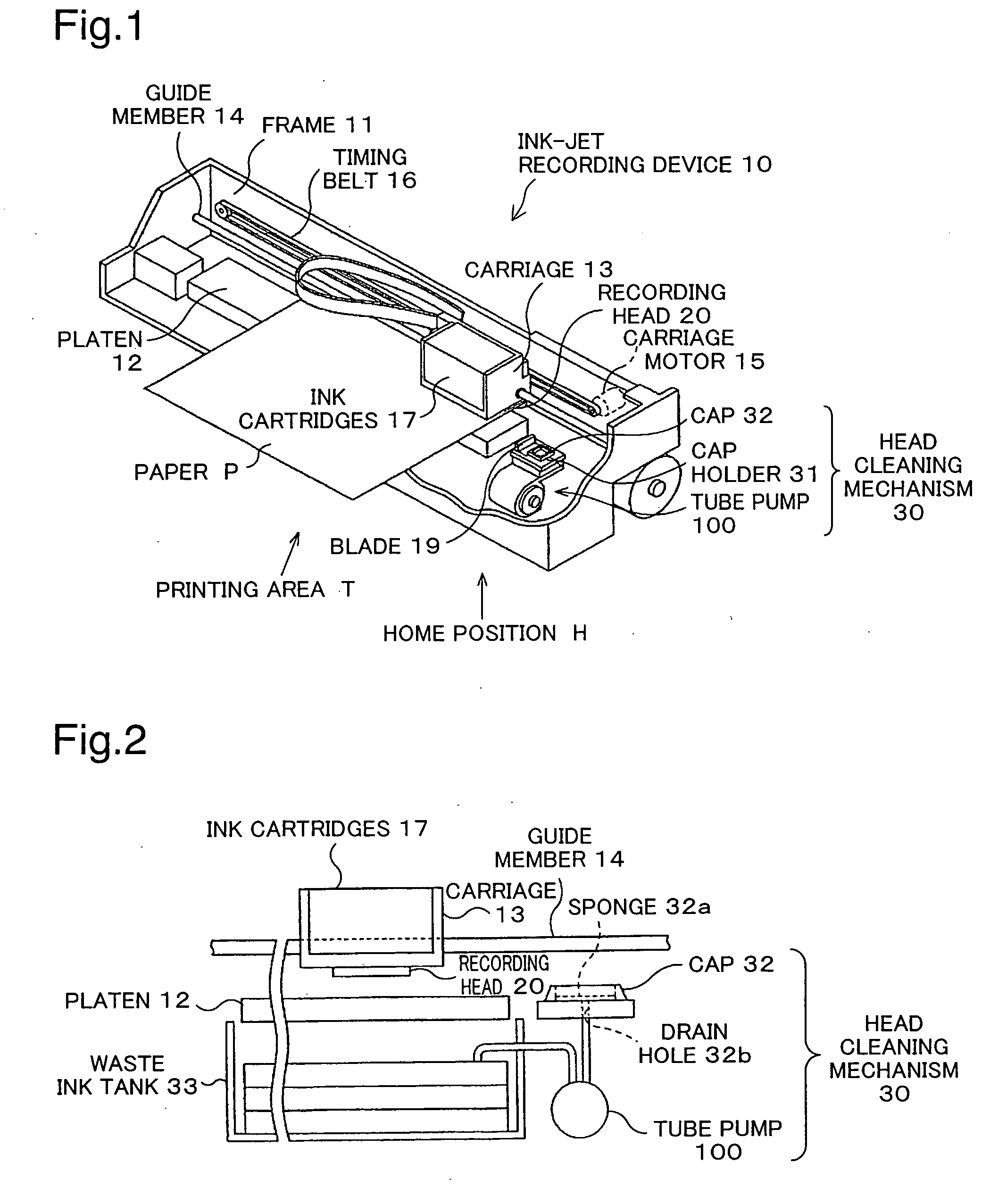
An ink-jet recording head of this design ejects ink through nozzles onto recording paper or other medium, and thus there is a risk that ink might not be ejected smoothly if the ink in proximity to the nozzles should become viscous, or if air bubbles should become entrained in the nozzles.
However there was the problem that, as shown in FIG. 9B, in this state, the tube 75 does not sufficiently collapse so that some gaps S remain within the tube and an adequate negative pressure cannot be created during subsequent recovery.
Since excessive compression of the tube 75 in this way creates strong reaction force, a correspondingly high level of torque is required of the tube pump motor, which created the problem of lower efficiency of the tube pump.

Method used


Image

  • Tube and tube pump
  • Tube and tube pump
  • Tube and tube pump

Examples


modified example 1

[0064]The present invention is not limited to ink-jet recording devices, and is applicable analogously to recording heads for use in printers and other such image recording devices; to colorant ejection heads used in the production of color filters for liquid crystal displays and the like; to electrode material ejection heads used for forming electrodes of organic EL displays, FED (field emission displays) and the like; liquid ejection devices that employ liquid ejection heads for ejecting liquids, such as bioorganic substance ejection heads used in biochip manufacture; sample material ejection devices for precision pipettes, and the like.

modified example 2

[0065]The present invention is not limited to tube pumps for liquids, and is applicable as well to tube pumps for gases, and to tube pumps for fluids in general.


PUM


Abstract

The tube 110 has a hollow portion 111 and a wall portion 112. The tube 110 has mutually contacting wall portions 111a that become compressed in such a way that the wall portion 112 comes into mutual contact in the hollow portion 111 through compression by a compressing mechanism 120, and is designed so that the mutually contacting wall portions 111a come into mutual contact, and the mutually contacting wall portions 111a recover upon release of the compressing mechanism. The mutually contacting wall portions 111a have readily contacting portions C1 that come into mutual contact at a certain level of compressing force, and contact resistant portions S1 that come into mutual contact only at a higher level of compressing force than in the readily contacting portions C1. The thickness of the wall portion 12 around the hollow portion 11 varies so that the readily contacting portions C1 are subjected to greater force than the contact resistant portions S1.

Description

CROSS REFERENCE TO RELATED APPLICATIONS[0001]The present application claims the priority based on Japanese Patent Applications No. 2006-24158 filed on Feb. 1, 2006, and No. 2006-347559 filed on Dec. 25, 2006, the disclosures of which are hereby incorporated by reference in their entireties.BACKGROUND OF THE INVENTION[0002]1. Field of the Invention[0003]The present invention relates to a tube pump for pumping fluids.[0004]2. Description of the Related Art[0005]Ink-jet type recording devices to date have employed ink-jet recording heads for ejecting ink onto recording paper or other media. An ink-jet recording head of this design ejects ink through nozzles onto recording paper or other medium, and thus there is a risk that ink might not be ejected smoothly if the ink in proximity to the nozzles should become viscous, or if air bubbles should become entrained in the nozzles. For this reason, ink-jet type recording devices are equipped with a head cleaning unit in order to avoid such ph...

Claims


Application Information

Patent Timeline
IPC IPC(8): F04B17/00
CPCB41J2/16523F04B49/20F04B43/1238F04B27/24B41J2/17B41J2/175
Inventor HARADA, SHUHEITAKAMOTO, TETSUYAMORI, TAKESHI
Owner SEIKO EPSON CORP
Learn More