
Voltage detecting device

Active Publication Date: 2007-07-26
YAZAKI CORP
View PDF1 Cites 43 Cited by
  • Summary
  • Abstract
  • Description
  • Claims
  • Application Information

AI Technical Summary

Benefits of technology

[0008]It is therefore an objective of the present invention to solve the above problem and to provide a voltage detecting device, by which when secondary batteries connected in series is divided into a plurality of modules (i.e. blocks) and a voltage of each secondary battery in each module is detected by a CPU disposed per module, the detection error of the detected voltage among the respective modules can be corrected with a low cost.
[0012]With the construction described above, since a relative error between the respective voltage detecting means is computed and the corrections can be carried out on the basis of the relative error, therefore even if a high-accuracy reference voltage and high-accuracy A / D converter are not used in the voltage detecting means, an equalizing error of each secondary battery can be removed with a low cost and each secondary battery can be used efficiently.
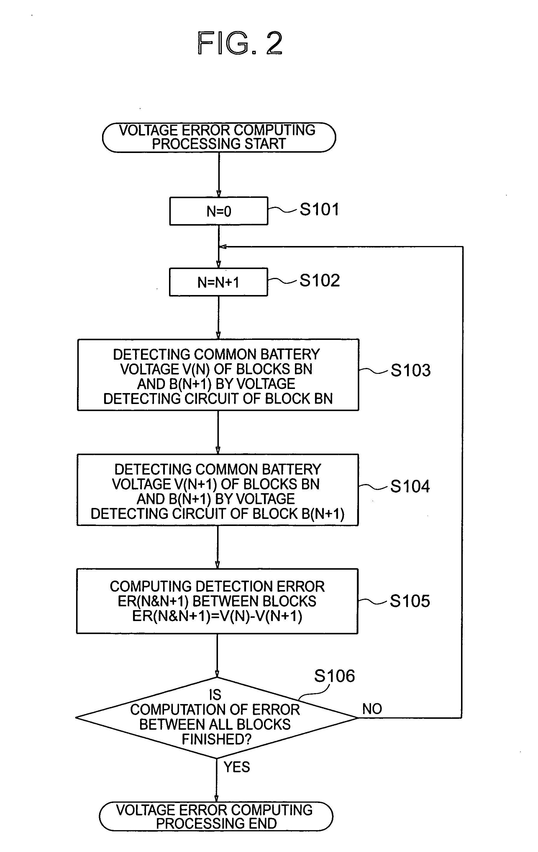
[0014]With the construction described above, the detection error between the two voltage detecting means adjacent to each other can be computed easily.

Problems solved by technology

That is, as for the HEV, this undesirable phenomenon makes so-called an assist and regeneration insufficient, wherein the assist means a supplement of battery energy with respect to gasoline upon hill-climbing and the regeneration means regeneration of energy to the battery, thereby causing deterioration in a vehicle dynamic characteristic or fuel efficiency.
In the conventional voltage detecting device described above, due to unevenness of a reference voltage used for detecting a voltage of each module and unevenness of accuracy of an A / D converter, a detection error takes place among the modules.
If the detection error among the modules is large, an equalizing error takes place when the SOC of each secondary battery is equalized and therefore, each secondary battery could not be used efficiently.
However, in such a case, it is necessary to have high-accuracy reference voltage and high-accuracy A / D converter for the respective modules, thereby causing a cost-up.

Method used


Image

  • Voltage detecting device
  • Voltage detecting device
  • Voltage detecting device

Examples


Embodiment Construction

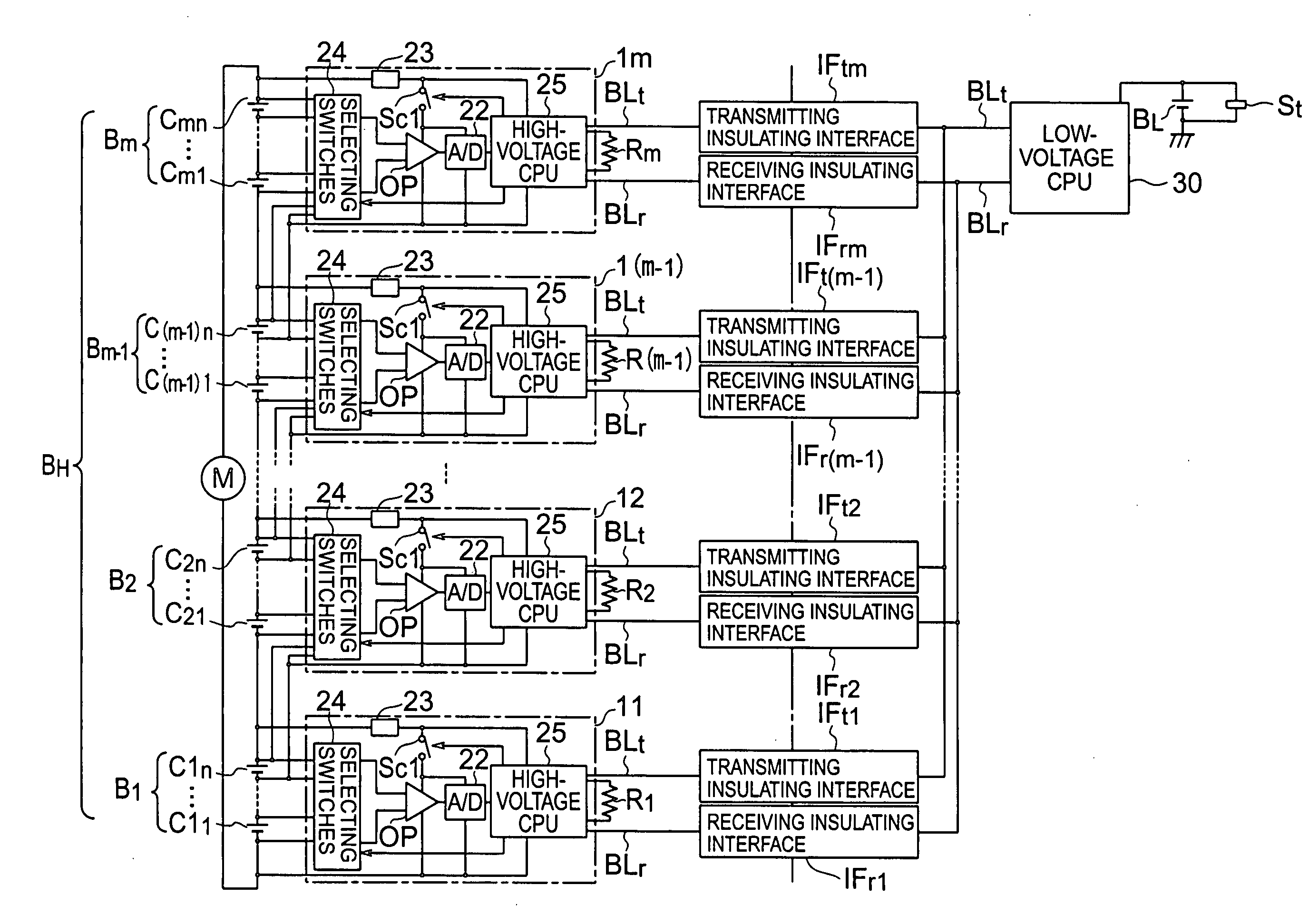
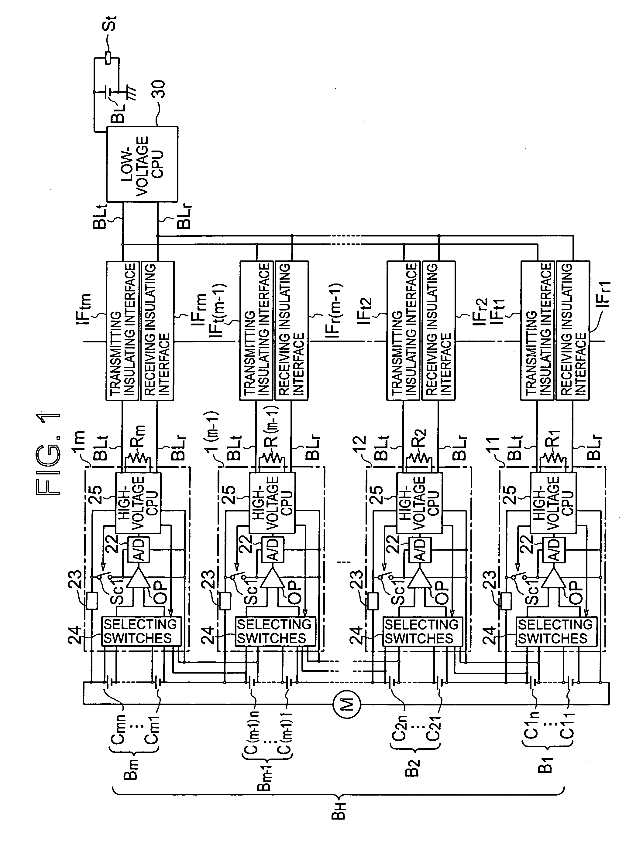
[0023]In the following, the preferred embodiments of the present invention will be explained with reference to the attached drawings. FIG. 1 shows a circuit illustrating a preferred embodiment of a voltage detecting device according to the present invention. A reference numeral BL denotes a low-voltage battery. For example, the low-voltage battery BL consists of one secondary battery as shown in FIG. 1. The low-voltage battery BL is used as a drive source of a starter St for starting an engine. An alternator or the like as a battery charger is connected to both ends of the low-voltage battery BL according to a need.

[0024]A reference numeral BH in FIG. 1 denotes a high-voltage battery. In a HEV which uses both an engine and an electric motor M as a traveling drive source, the high-voltage battery BH is used as an electric source of the electric motor M. The electric motor M as a load is connected to both ends of the high-voltage battery BH according to a need. An alternator (not show...


PUM


Abstract

A voltage detecting device for an on-vehicle high-voltage battery in which secondary batteries are connected in series, the on-vehicle high-voltage battery being divided into blocks each including at least one secondary battery, includes: voltage detecting means each assigned to each block for detecting a voltage of each secondary battery included in the block; and control means for controlling the voltage detecting means, wherein a common secondary battery is selected from the secondary batteries, a voltage of the common secondary battery being detectable by two voltage detecting means, wherein the control means causes the two voltage detecting means to detect the voltage of the common secondary battery, computes a detection error between the two voltage detecting means from the detected voltage values of the common secondary battery, and makes corrections in voltage values detected by the two voltage detecting means on the basis of the computed detection error.

Description

BACKGROUND OF THE INVENTION[0001](1) Field of the Invention[0002]The present invention relates to a voltage detecting device, particularly to a voltage detecting device for detecting a voltage across a plurality of secondary batteries connected in series, which constitute an on-vehicle high-voltage battery.[0003](2) Description of the Related Art[0004]Recently, a hybrid electric-internal combustion vehicle (hereinafter, HEV), which travels by using both an engine and an electric motor, has been widely used. The HEV has two kinds of batteries consisting of a low-voltage (such as about 12V) battery for starting an engine and a high-voltage battery for driving an electric motor. The high-voltage battery provides a high voltage by connecting a plurality of secondary batteries such as nickel-hydrogen batteries or lithium batteries, each said secondary battery being an electric cell or a unit cell.[0005]As for the high-voltage battery described above, a voltage of each secondary battery, ...

Claims


Application Information

Patent Timeline
IPC IPC(8): H02J7/00
CPCB60L11/1866B60L11/1868B60L2240/547Y02T10/7066Y02T10/7005Y02T10/7011Y02T10/7061G01R31/3658B60L58/20B60L58/22G01R31/396Y02T10/70
Inventor ISHIKAWA, SATOSHIOKAMOTO, HAJIME
Owner YAZAKI CORP
Learn More