
Flow straightener for axial fans, particularly for conditioning systems

a technology of axial fans and straighteners, which is applied in the direction of wind turbines, liquid fuel engines, wind turbines with parallel air flow, etc., can solve the problems of parasitic recirculation, inherent limitation of a generic axial fan, and limitations of the output air jet shape of the axial fan used for cold air distribution in enclosed spaces

Inactive Publication Date: 2007-07-19
EMERSON NETWORK POWER SRL
View PDF8 Cites 0 Cited by
  • Summary
  • Abstract
  • Description
  • Claims
  • Application Information

AI Technical Summary

Benefits of technology

[0023]The aim of the present invention is to provide a flow straightener for axial fans particularly for conditioning systems which is capable of solving the drawbacks of known types of straightener.
[0024]Within this aim, an object of the present invention is to provide a flow straightener which is capable of reducing the above cited problems linked to the correct operation of a ceiling-mounted conditioning unit with vertical axial fan.
[0025]Another object of the present invention is to provide a straightener which limits parasitic recirculations of air, rendering the air flow that exits from the axial fan less conical than the air flows that exit from known types of straightener.
[0026]Another object of the present invention is to provide a flow straightener which improves the stratification of the air in the enclosed space in which the conditioning unit with which it is associated works.
[0028]A further object of the present invention is to provide a flow straightener for axial fans particularly for conditioning systems which can be manufactured cheaply with known systems and technologies.

Problems solved by technology

This simplified diagram reveals the first inherent limitation of a generic axial fan, i.e., the parasitic recirculation of air which occurs on the entire perimeter of the disk generated by the rotation of the impeller.
One of the limitations shown by the use of axial fans for the distribution of cold air in enclosed spaces is the shape of the output air jet.
This is one of the reasons why axial fans are mainly used in suction mode, since the manner in which the output air jet is constituted is of limited importance for the application.
This second type of straightener, although being better than the first one, can be very bulky, but most of all is generally very expensive, since the profile of the vanes must be studied and built accurately also according to the profile of the vanes of the impeller of the fan.
The problem to be solved for these conditioning units is therefore the orientation of the air flow which exits downward.
Another problem for these conditioning units with an axial fan with descending vertical action is said parasitic air recirculation, which occurs on the entire perimeter of the disk formed by the rotation of the impeller.
This recirculation in fact reduces the efficiency of said conditioning unit and consequently has a negative effect also on the other associated machines, such as remote condensing units, water cooling units with air condensation, and the like.

Method used


Image

  • Flow straightener for axial fans, particularly for conditioning systems
  • Flow straightener for axial fans, particularly for conditioning systems
  • Flow straightener for axial fans, particularly for conditioning systems

Examples


first embodiment

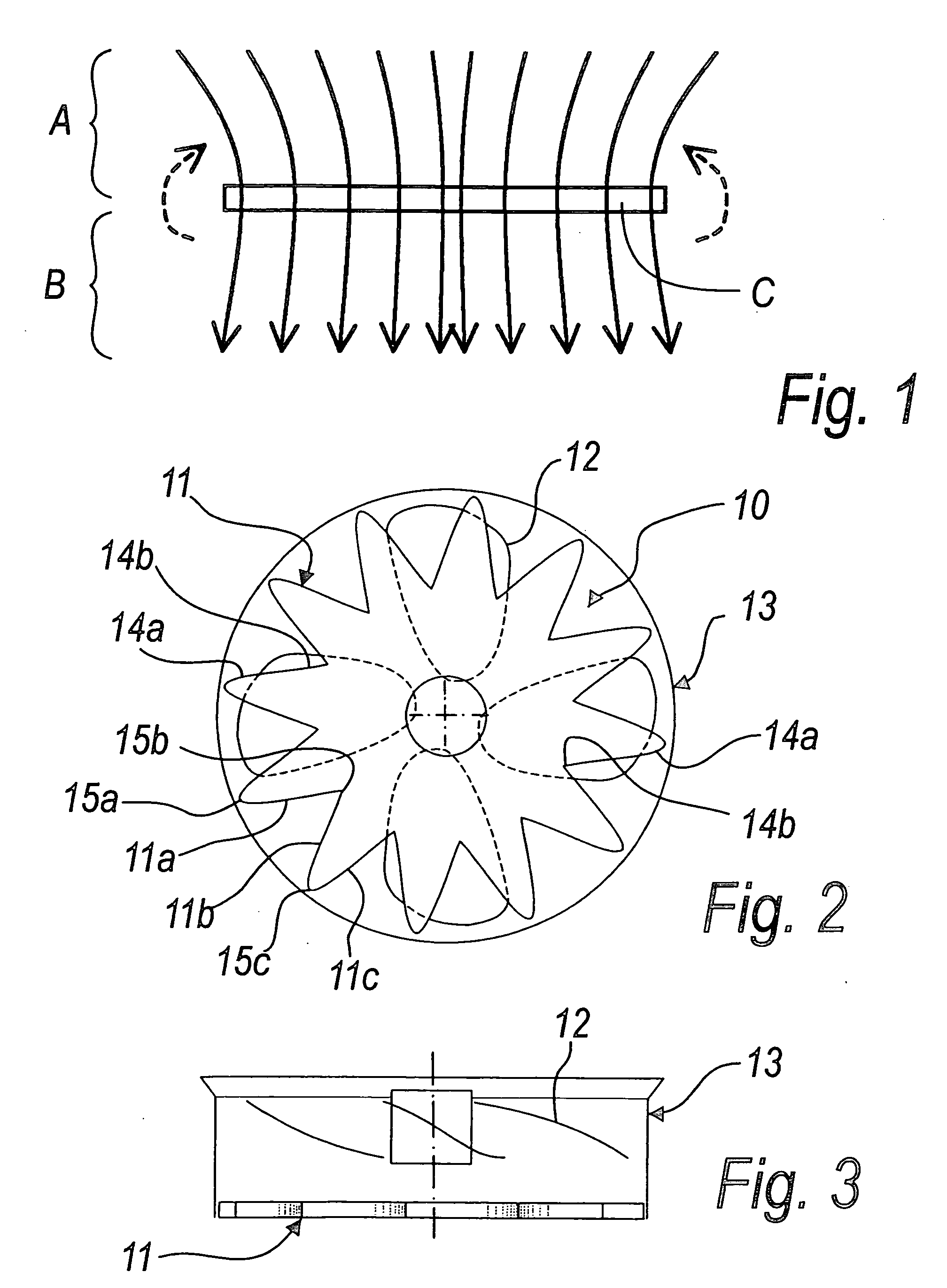
[0038]With reference to the figures, a flow straightener for axial fans particularly for conditioning systems according to the invention is generally designated by the reference numeral 10 in its first embodiment, which is shown in FIGS. 2 to 5.

[0039]The straightener 10 is constituted by a plurality of flat deflection walls, of which three 11a, 11b, 11c are shown in FIG. 2 by way of example and form a substantially star-shaped profile or element 11.

[0040]The profile or element 11 has a central axis thereof and is adapted to be arranged coaxially to an impeller 12 of an axial fan 13 with which it is associated and proximate to said impeller.

[0041]The thickness extension of the profile 11 lies substantially in the direction of the axis of the impeller 12 and therefore vertically in the case of an axial fan of a ceiling-mounted conditioning unit.

[0042]The flat walls 11a, 11b, 11c are each constituted by a metallic lamina which is joined by its ends 14a and 14b to a contiguous additiona...

second embodiment

[0046]In the straightener according to the invention, shown in FIG. 6 and designated by the reference numeral 110 therein, the vertices 115a onward are substantially angular, and a substantially straight wall 111a and a curved wall 111b join thereat.

third embodiment

[0047]In the straightener according to the invention, shown in FIG. 7 and designated by the reference numeral 210 therein, the vertices 115 are curved.

[0048]The profile or element 11, 111 and 211 which provides the straightener according to the invention is obtained by bending a strip of metal plate.

[0049]As an alternative, the straightener 10, 110, 210 can be obtained by molding plastic material.

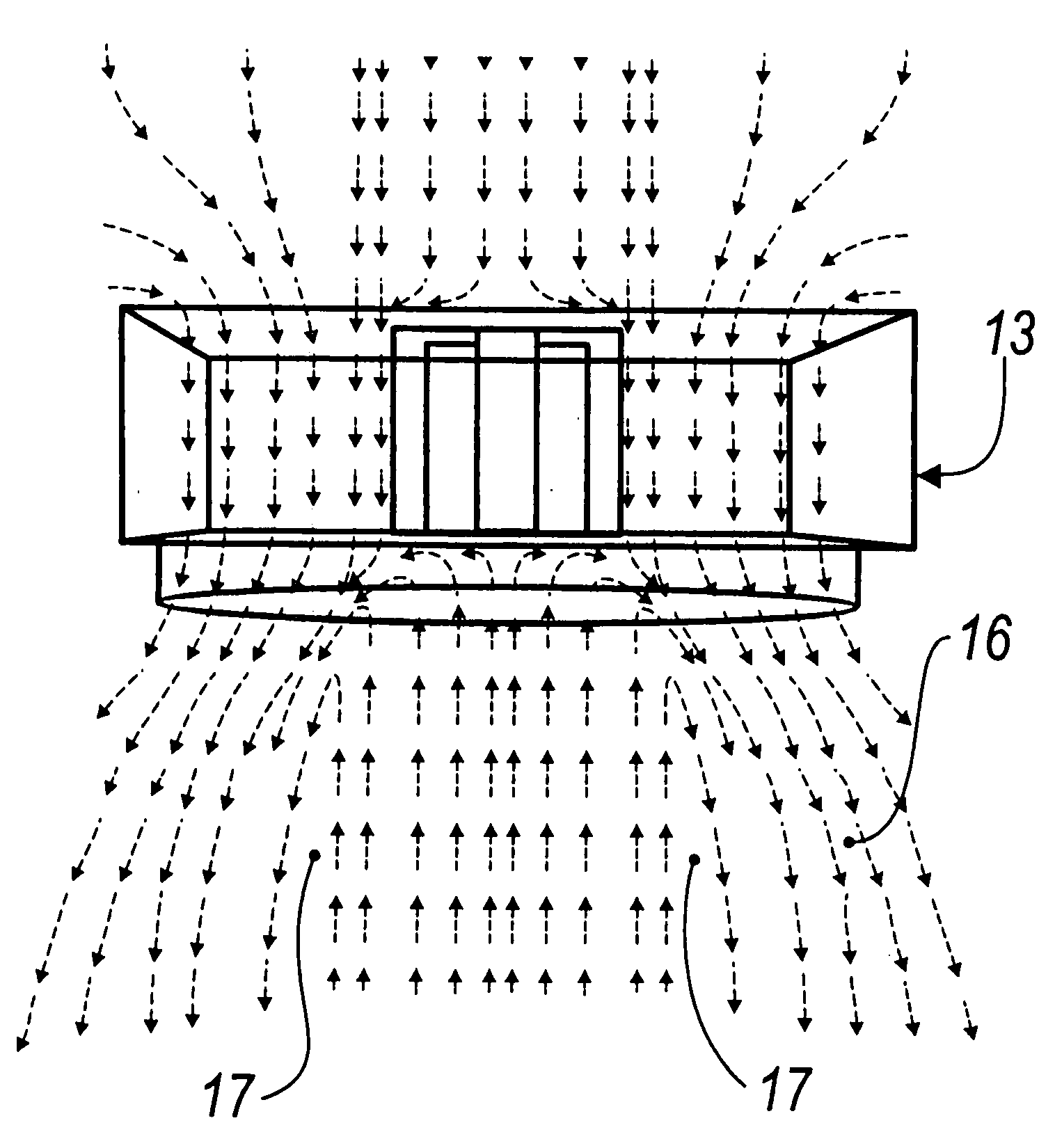
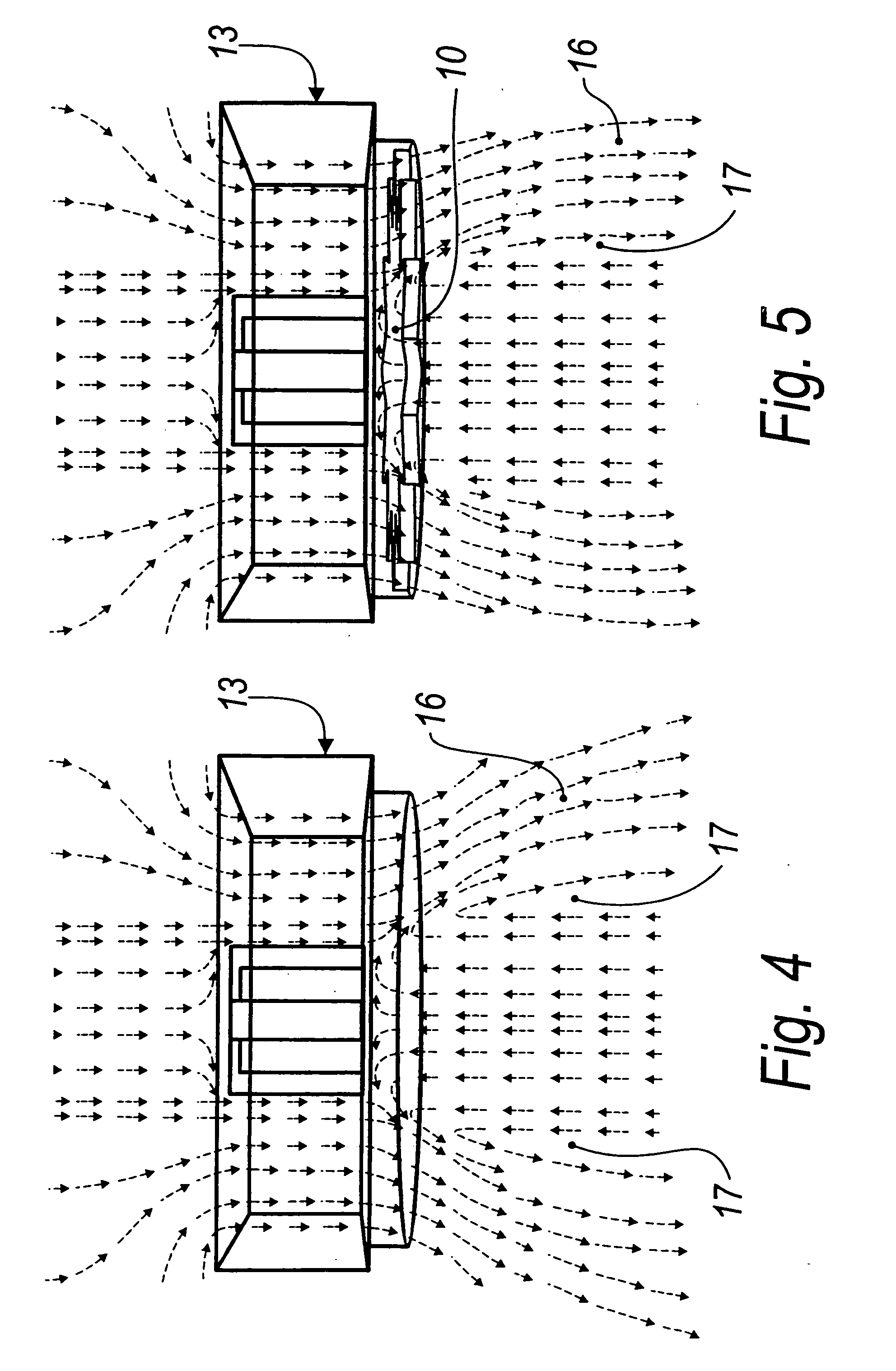
[0050]FIG. 4 is a side view of a measurement of the behavior of the air flow determined by an axial fan 13 without a flow straightener.

[0051]The conical shape, which opens downward, of the profile 16 of the faster air flow and the extent of recirculation regions 17 are clearly visible.

[0052]FIG. 5 illustrates the same side view as FIG. 4, related to the axial fan 13 provided with the straightener 10 according to the invention.

[0053]In said figure, the profile 16 of the faster air flow is substantially cylindrical and the recirculation regions 17 are greatly reduced.

[0054]In practice it has ...


PUM


Abstract

A flow straightener for axial fans particularly for conditioning systems, being constituted by a plurality of flat deflection walls, which form a substantially star-shaped profile which is adapted to be arranged coaxially and proximate to the impeller of the axial fan with which it is associated.

Description

[0001]The present invention relates to a flow straightener for axial fans, particularly for conditioning system.BACKGROUND OF THE INVENTION[0002]In conditioning and refrigeration technologies, fans of the axial type are used when it is necessary to generate air flows characterized by a high flow-rate / head ratio, i.e., when large amounts of air have to be moved over short paths or have to pass through means which have a high load loss (such as for example a high-efficiency filtration system).[0003]The operation of a free axial impeller, shown schematically in FIG. 1, generates two volumes A and B at different pressures, which are divided by the disk-like band C occupied by the impeller in its rotary motion.[0004]This simplified diagram reveals the first inherent limitation of a generic axial fan, i.e., the parasitic recirculation of air which occurs on the entire perimeter of the disk generated by the rotation of the impeller.[0005]One of the limitations shown by the use of axial fan...

Claims


Application Information

Patent Timeline
Patent Type & Authority Applications(United States)
IPC IPC(8): F01D9/00
CPCF04D29/541F04D25/08
Inventor LAZZARATO, MORENOBREGANTIN, MARISTELLALAZZARATO, MARCOGRIGOLETTO, GIULIANOMICHIELI, STEFANOZUANNA, ANDREA DALLA
Owner EMERSON NETWORK POWER SRL
Learn More