
Secondary Side Post Regulation for LED Backlighting

a backlighting and led technology, applied in the field of led based lighting, can solve the problems of chang not teaching the use of pwm to achieve an overall luminance, inconvenient operation, and inability to achieve the overall luminance of the pwm,

Inactive Publication Date: 2007-07-12
POLARIS POWERLED TECH LLC
View PDF16 Cites 146 Cited by
  • Summary
  • Abstract
  • Description
  • Claims
  • Application Information

AI Technical Summary

Problems solved by technology

Unfortunately, excess power dissipation in the regulator results in an overall inefficient circuit, particularly if the voltage is unregulated and varies over a wide range.
Unfortunately, Chang does not teach the use of PWM to achieve an overall luminance in cooperation with the secondary side post regulator controllers.
The use of PWM leads to significant voltage output transients which results in distorted LED current waveforms causing significant inaccuracy in color and luminance of LCD monitors.

Method used


Image

  • Secondary Side Post Regulation for LED Backlighting
  • Secondary Side Post Regulation for LED Backlighting
  • Secondary Side Post Regulation for LED Backlighting

Examples


Embodiment Construction

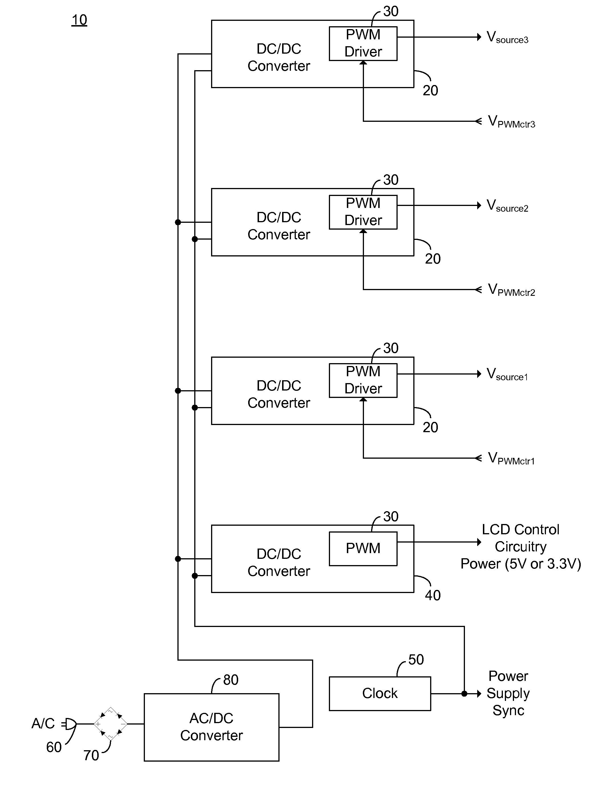
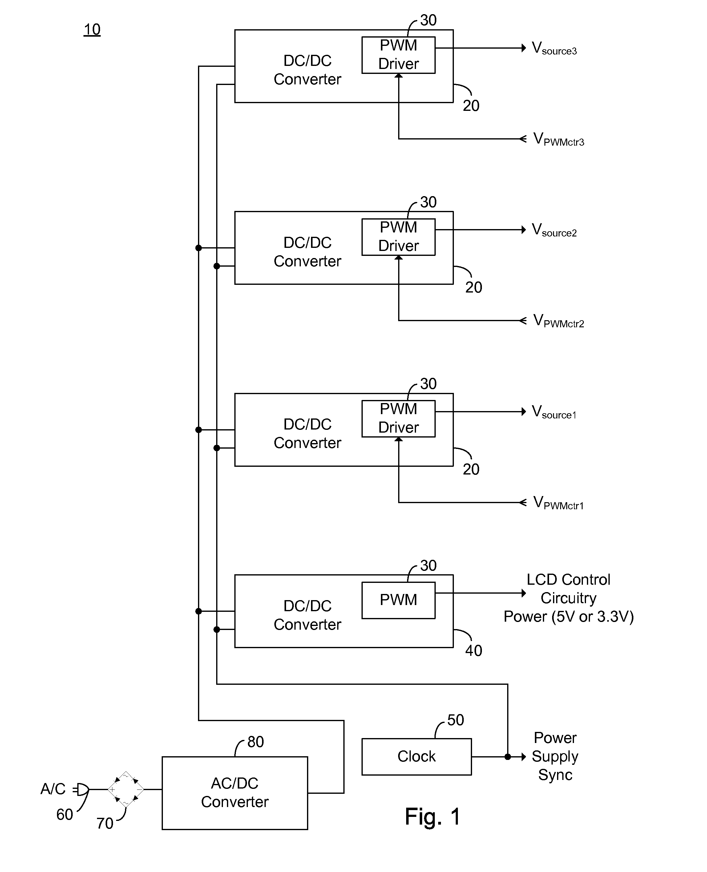
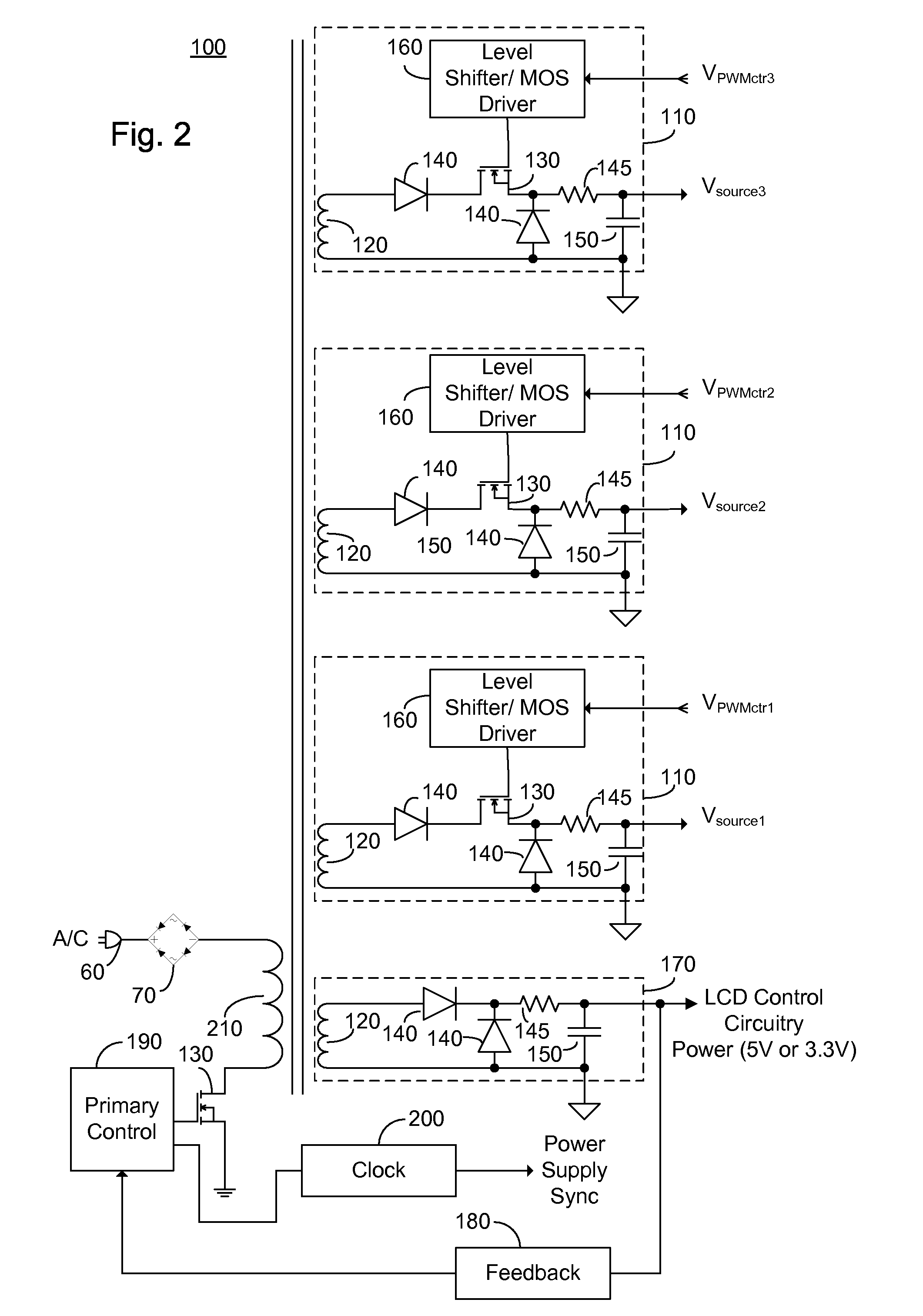
[0034] The present embodiments enable a secondary side post regulator arrangement for a plurality of LED strings. For each secondary winding of the secondary side post regulator, a first electronically controlled switch is provided arranged to control the power output, and a LED string is connected thereto. A second electronically controlled switch is further connected in series with the LED string, arranged to receive a PWM signal, thereby pulsing current through the LED string. A current sensing element is further provided outputting a voltage representation of the current through the LED string, and a synchronized sampler is provided arranged to sample the voltage representation during the on period of the second electronically controlled switch. The sampled and held voltage representation is compared with a reference signal and fed back to control the first electronically controlled switch. Thus, the voltage output associated with each secondary winding is controlled, responsive...


PUM


Abstract

A secondary side post regulator arrangement for a plurality of LED strings. For each secondary winding, a first electronically controlled switch is provided arranged to control the power output, and a LED string is connected thereto. A second electronically controlled switch is further connected in series with the LED string, arranged to receive a PWM signal, thereby pulsing current through the LED string. A current sensing element is further provided outputting a voltage representation of the current through the LED string, and a synchronized sampling circuit is provided arranged to sample the voltage representation during the on period of the second electronically controlled switch. The sampled and held voltage representation is compared with a reference signal and fed back to control the first electronically controlled switch. The voltage output associated with each secondary winding is controlled, responsive to the reference voltage.

Description

CROSS-REFERENCE TO RELATED APPLICATION [0001] This application claims priority from provisional patent application Ser. No. 60 / 757,466 filed Jan. 10, 2006, entitled “Variable Voltage Source for LED Backlighting”, the entire contents of which is incorporated herein by reference.BACKGROUND OF THE INVENTION [0002] The present invention relates to the field of LED based lighting and more particularly to a constant current source for a series LED string having a voltage control feedback. [0003] Light emitting diodes (LEDs) and in particular high intensity LED strings are rapidly coming into wide use. High intensity LEDs are sometimes called high power LEDs, high brightness LEDs, high current LEDs or super luminescent LEDs and are useful in a number of applications including backlighting for liquid crystal display (LCD) based monitors and televisions, collectively hereinafter referred to as a monitor. In a large LCD monitor typically the high intensity LEDs are supplied in a string of ser...

Claims


Application Information

Patent Timeline
Patent Type & Authority Applications(United States)
IPC IPC(8): G09G3/32
CPCG09G3/006H05B33/0872G09G2320/041G09G2320/043G09G2320/0606G09G2320/0633G09G2320/064G09G2320/0666G09G2330/02G09G2330/021G09G2330/06G09G2360/145H05B33/0815H05B33/0818H05B33/0869G09G3/3413H05B45/22H05B45/28H05B45/3725
Inventor PEKER, ARKADIYKORCHARZ, DROR
Owner POLARIS POWERLED TECH LLC
Learn More