
Data identification method and apparatus

a data identification and data technology, applied in the field of data identification methods and apparatuses, can solve the problems of complicated circuit configurations that are necessary for correlation detection, and achieve the effect of simplifying the arithmetic operation

Inactive Publication Date: 2007-07-12
SONY CORP
View PDF3 Cites 0 Cited by
  • Summary
  • Abstract
  • Description
  • Claims
  • Application Information

AI Technical Summary

Benefits of technology

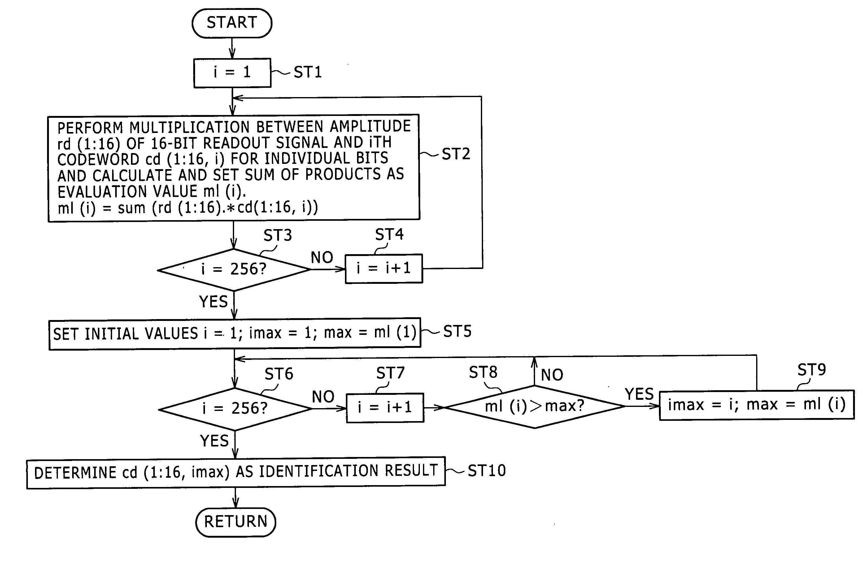
[0032] According to an embodiment of the present invention, there is provided a data identification method for identifying, from within a readout signal from a recording medium on or in which user data of k bits are recorded using a recording modulation code wherein m bits from among n bits which compose one codeword have a value of “1” while the remaining n-m bits have another value of “0”, the data, n and m being integers, including a first step of delimiting the readout signal in a unit of a codeword and adding, with regard to one of the n-bit codewords obtained by the delimiting, an amplitude of the readout signal of the bits of “1” to 2ˆk different codewords which may possibly be recorded and setting results of the addition as evaluation values, and a second step of finding a maximum value among the 2ˆk evaluation values and outputting the maximum value as an evaluation value.
[0037] The data identification method and apparatus are advantageous in that arithmetic operation can be simplified while an identification performance similar to that of correlation detection is maintained.

Problems solved by technology

Therefore, the correlation detection has a problem that a very much complicated circuit configuration is necessary for the correlation detection.

Method used


Image

  • Data identification method and apparatus
  • Data identification method and apparatus
  • Data identification method and apparatus

Examples


Embodiment Construction

[0049] A data identification method to which the present invention is suitable for use with hologram recording and so forth wherein the sparse code is used as a recording modulation code. According to the present embodiment, there is provided a data identification method by which the substance of arithmetic operation is simplified while an identification performance similar to that of correlation detection which achieves the highest identification performance is maintained.

[0050] First, the data identification method to which the present invention is applied and which is applied to a hologram recording and reading system is described.

[0051] First, a sparse code (recording modulation code) used in the present embodiment is described.

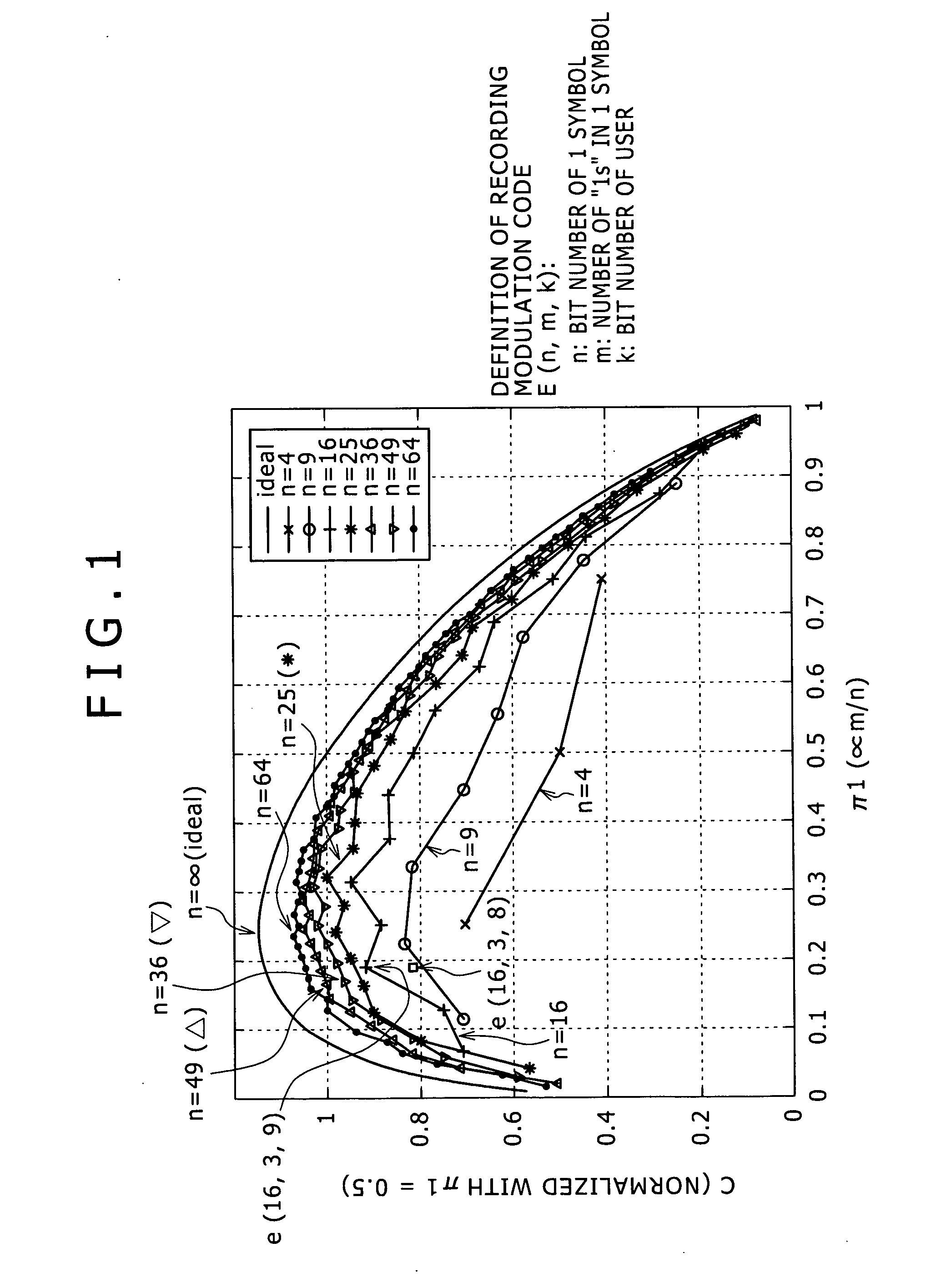
[0052] As described hereinabove, an arbitrary sparse code is defined by E(n, m, k) using a bit number n of bits of one symbol, a bit number m of bits having the value “1” in one symbol, and a bit number k of bits of a user. Here, the “symbol” is a mini...


PUM


Abstract

Disclosed herein is a data identification method for identifying, from within a readout signal from a recording medium on or in which user data of k bits are recorded using a recording modulation code wherein m bits from among n bits which compose one codeword have a value of “1” while the remaining n-m bits have another value of “0”, the data, n and m being integers including, a first step of delimiting the readout signal in a unit of a codeword and adding, with regard to one of the n-bit codewords obtained by the delimiting, an amplitude of the readout signal of the bits of “1” to 2ˆk different codewords which may possibly be recorded and setting results of the addition as evaluation values, and a second step of finding a maximum value among the 2ˆk evaluation values and outputting the maximum value as an evaluation result.

Description

CROSS REFERENCES TO RELATED APPLICATIONS [0001] The present invention contains subject matter related to Japanese Patent Application JP 2006-002980 filed in the Japanese Patent Office on Jan. 10, 2006, the entire contents of which being incorporated herein by reference. BACKGROUND OF THE INVENTION [0002] 1. Field of the Invention [0003] This invention relates to a data identification method and apparatus which identifies, from within a readout signal from a recording medium on or in which user data are recorded using a recording modulation code called sparse code, the data. [0004] 2. Description of the Related Art [0005] Recently, research and development of an information processing apparatus which makes use of the principle of hologram recording are carried out actively as disclosed, for example, in “Holographic encouraged for implementation of a terabyte disk”, Nikkei Electronics, Aug. 15, 2005, No. 906, pp. 51-58 (hereinafter referred to as Non-Patent Document 1). [0006] It is a...

Claims


Application Information

Patent Timeline
Patent Type & Authority Applications(United States)
IPC IPC(8): H03M7/00
CPCH03M5/145G11B7/0065
Inventor HARA, MASAAKITANAKA, KENJI
Owner SONY CORP
Learn More