Method and control interface for food preparation on a cooking appliance

a technology for cooking appliances and user interfaces, applied in the direction of electric/magnetic/electromagnetic heating, domestic stoves or ranges, lighting and heating apparatus, etc., can solve the problems of affecting the cooking effect of the cooking applian

Inactive Publication Date: 2007-07-12
VIKING RANGE
View PDF6 Cites 194 Cited by
  • Summary
  • Abstract
  • Description
  • Claims
  • Application Information

AI Technical Summary

Benefits of technology

[0005] Disclosed according to the subject application is a graphical user interface for a cooking appliance adapted to enable a user to direct and control the cooking appliance. The graphical user interface generally includes a plurality of user selectable and controllable cooking operations, each of which operation is accessible through one of a plurality of layers of screens provided by the graphical user interface. The operations generally include such example operations as a refrigerate operation, a cook now operation, a cook later operation, etc. The refrigerate operation is suitably adapted to cause the cooking appliance to maintain an internal temperature adequate for refrigerating a food item placed therein. The cook now operation is adapted to enable the user to direct the cooking appliance to immediately cook a food item. The cook later operation is adapted to enable the user to direct the cooking appliance to cook a food item at a specified time and date.

Problems solved by technology

These components often suffer from poor construction, a tendency to break, and a tendency to become detached from the appliance.
Conventional cooking appliances typically offer a limited number of cooking operations.
However, these operational parameters are often inadequate to provide a fully functional cooking apparatus.

Method used


Image

  • Method and control interface for food preparation on a cooking appliance
  • Method and control interface for food preparation on a cooking appliance
  • Method and control interface for food preparation on a cooking appliance

Examples


Embodiment Construction

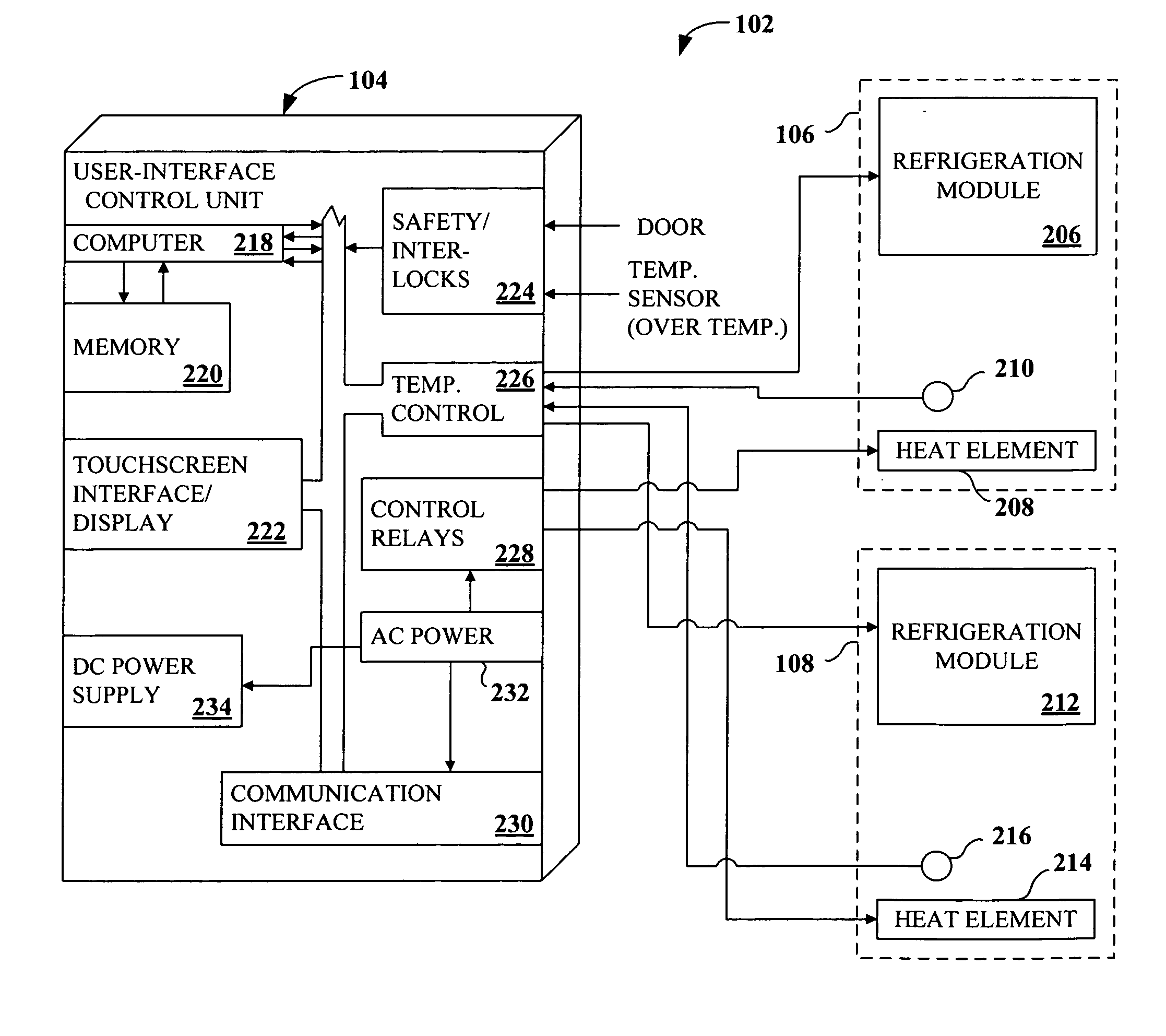
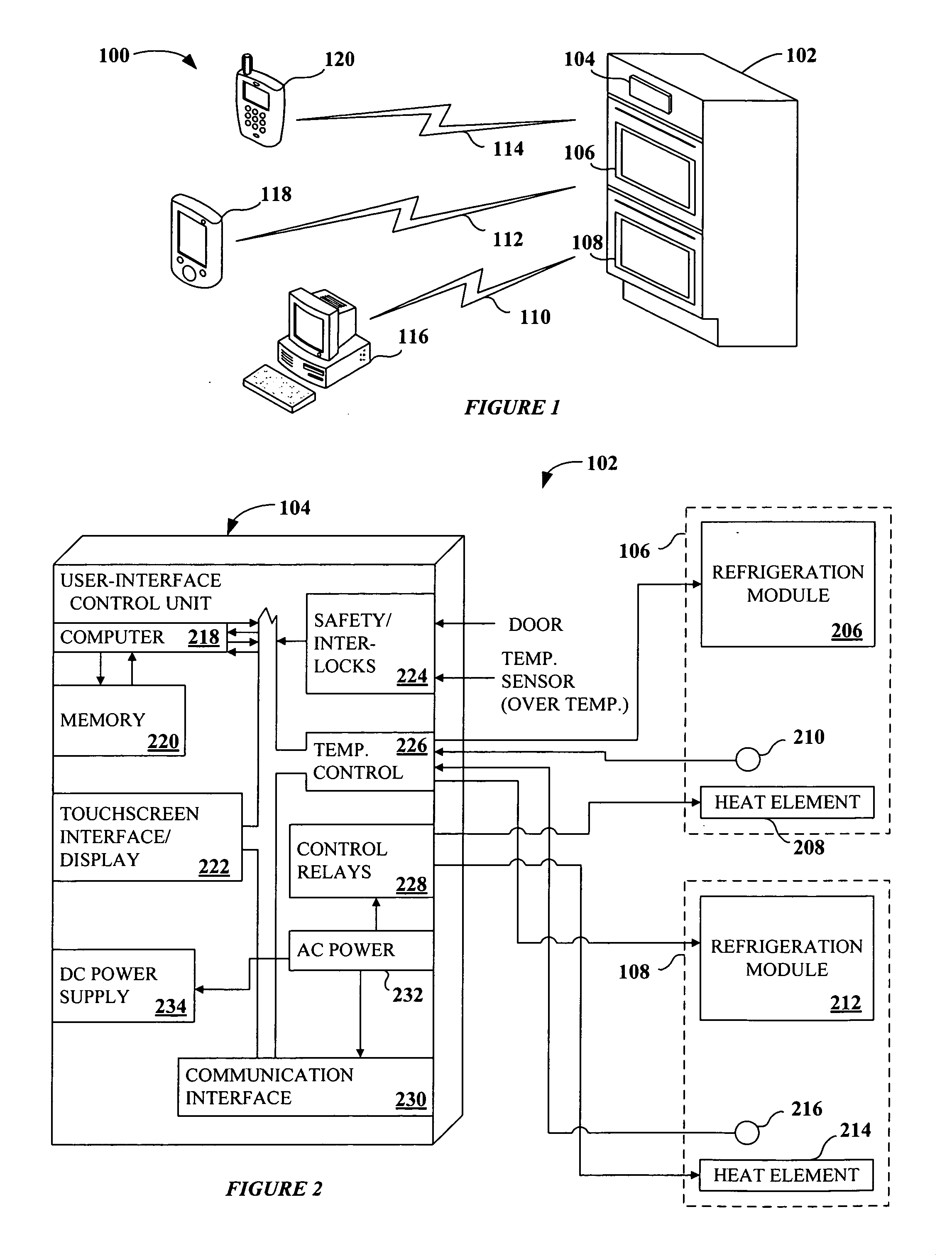
[0166] The subject application is directed to control systems for cooking appliances. More particularly, the subject application is directed to a control interface for food preparation and a method for food preparation using the control interface. FIG. 1 illustrates an exemplary system 100 employing the present invention. In the preferred embodiment of the present invention, the control interface is implemented as a graphical user-interface (“GUI”).

[0167] As shown in FIG. 1, the system 100 includes one or more remote devices, illustrated as a desktop computer 116, a personal data assistant (PDA) 118, and a web-enabled cellular telephone 120. The system also includes a cooking appliance 102. In the preferred embodiment, the cooking appliance 102 suitably comprises a refrigerator / oven, capable of both refrigerating and cooking food items. The cooking appliance 102 further comprises a top compartment 106, suitably equipped for both heating and cooling a food item, a bottom compartment...


PUM


Abstract

A graphical user interface adapted to enable a user to direct and control a cooking appliance. The graphical user interface generally enables a plurality of cooking appliance operations through associated layers of screens, such as a refrigerate operation, a cook now operation, a cook later operation, etc., and a plurality of cook settings, such as a bake setting, a roast setting, a broil setting, a warm setting, a convection bake setting, a convection roast setting, a convection broil setting, a convection defrost setting, etc. The graphical user interface is adapted to be integrated with and accessible through one or more of the cooking appliance, a handheld device, an Internet-accessible computer, etc.

Description

CROSS-REFERENCE TO RELATED APPLICATIONS [0001] This application is a continuation-in-part of PCT / US05 / 00443, filed Jan. 7, 2005, entitled, GRAPHICAL USER INTERFACE FOR A COOKING APPLIANCE, which claims priority to U.S. patent application Ser. No. 11 / 030,797, filed Jan. 7, 2005 entitled, GRAPHICAL USER INTERFACE FOR A COOKING APPLIANCE, which claims priority to U.S. Provisional Patent Application No. 60 / 634,826 filed Jan. 7, 2004 entitled, GRAPHICAL USER INTERFACE FOR A COOKING APPLIANCE, the entirety of which is incorporated herein.BACKGROUND OF THE INVENTION [0002] The present invention relates to a graphical user interface, and more particularly, the present invention relates to a graphical user interface for directing and controlling a cooking appliance. [0003] A cooking appliance is a device adapted to heat food to a desired temperature for consumption. A user typically directs operation of a conventional cooking appliance through a simple fixed control panel that usually includ...

Claims


Application Information

Patent Timeline
Patent Type & Authority Applications(United States)
IPC IPC(8): H05B1/02
CPCA47J27/62H05B6/6435F24C7/082A47J36/321
Inventor MANSBERY, DAVID I.
Owner VIKING RANGE
Why Eureka
Try Eureka