
Expanding single channel stimulator capability on multi-area stimulation programs

a multi-area stimulation and single-channel technology, applied in the field of tissue stimulation systems, can solve the problems of increasing the drain on the battery, inefficient use of the stimulator power supply, and increasing so as to reduce the number of stimulation channels

Inactive Publication Date: 2007-07-05
BOSTON SCI NEUROMODULATION CORP
View PDF39 Cites 35 Cited by
  • Summary
  • Abstract
  • Description
  • Claims
  • Application Information

AI Technical Summary

Benefits of technology

[0014] The present invention addresses the above and other advantages by providing a method of facilitating combining multiple stimulation channels into a reduced number of channels, preferably a single channel.
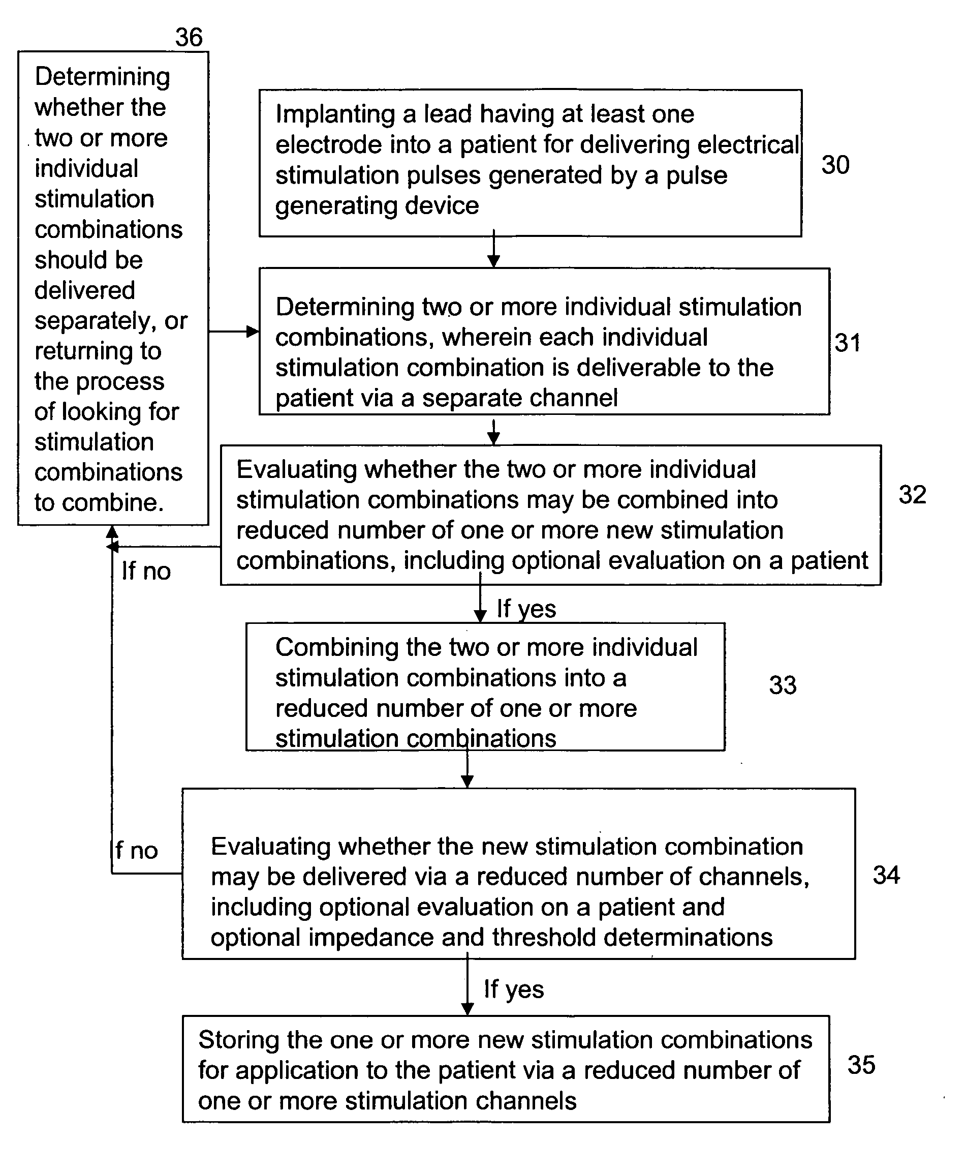
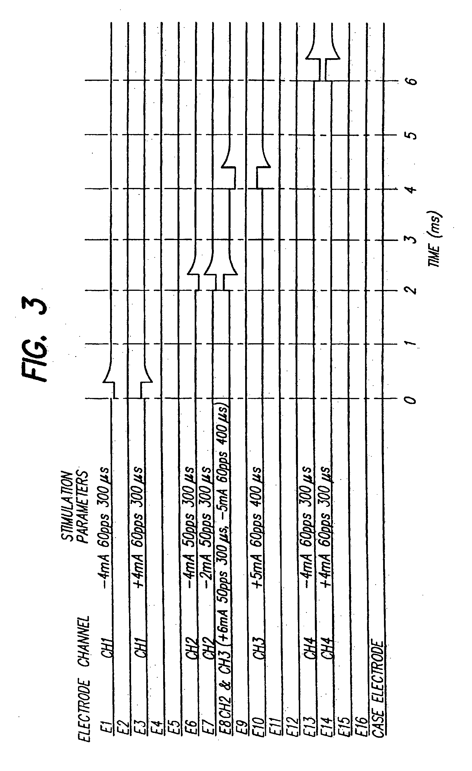
[0015] An embodiment includes a method of reducing the number of stimulation channels used for stimulation therapy. The method may include: (1) determining two or more stimulation combinations, wherein each stimulation combination is capable of inducing a corresponding therapeutic effect in a patient's body and wherein each stimulation combination is deliverable to the patient via a separate channel; (2) evaluating the two or more stimulation combinations to determine if the two or more combinations may be combined into a reduced number of new stimulation combinations; (3) combining the two or more stimulation combinations into a reduced number of new stimulation combinations; and (4) storing the new stimulation combinations for application to the patient via a reduced number of stimulation channels.
[0019] Another method of reducing the number of stimulation channels for a stimulation therapy may include: (1) determining two or more stimulation combinations, wherein each stimulation combination is capable of inducing a corresponding therapeutic effect in a patient's body and wherein each stimulation combination is deliverable to the patient via a separate channel; (2) evaluating the two or more stimulation combinations to determine if the two or more combinations may be combined into a reduced number of new stimulation combinations; (3) combining the two or more stimulation combinations into a reduced number of new stimulation combinations; (4) applying stimulation to the patient according to the new stimulation combinations via a reduced number of stimulation channels; and (5) evaluating the new stimulation combinations.
[0020] A tissue stimulation system may include: (1) a pulse generating device for generating electrical stimulation pulses; (2) at least one implanted lead including at least one electrode for delivering the electrical stimulation pulses generated by the pulse generating device; and (3) a programmer for programming two or more stimulation combinations to be generated by the pulse generating device to be delivered via one or more stimulation channels, wherein said programmer is capable of combining the stimulation combinations into a reduced number of new stimulation combinations to be delivered by the at least one electrode over a reduced number of stimulation channels.
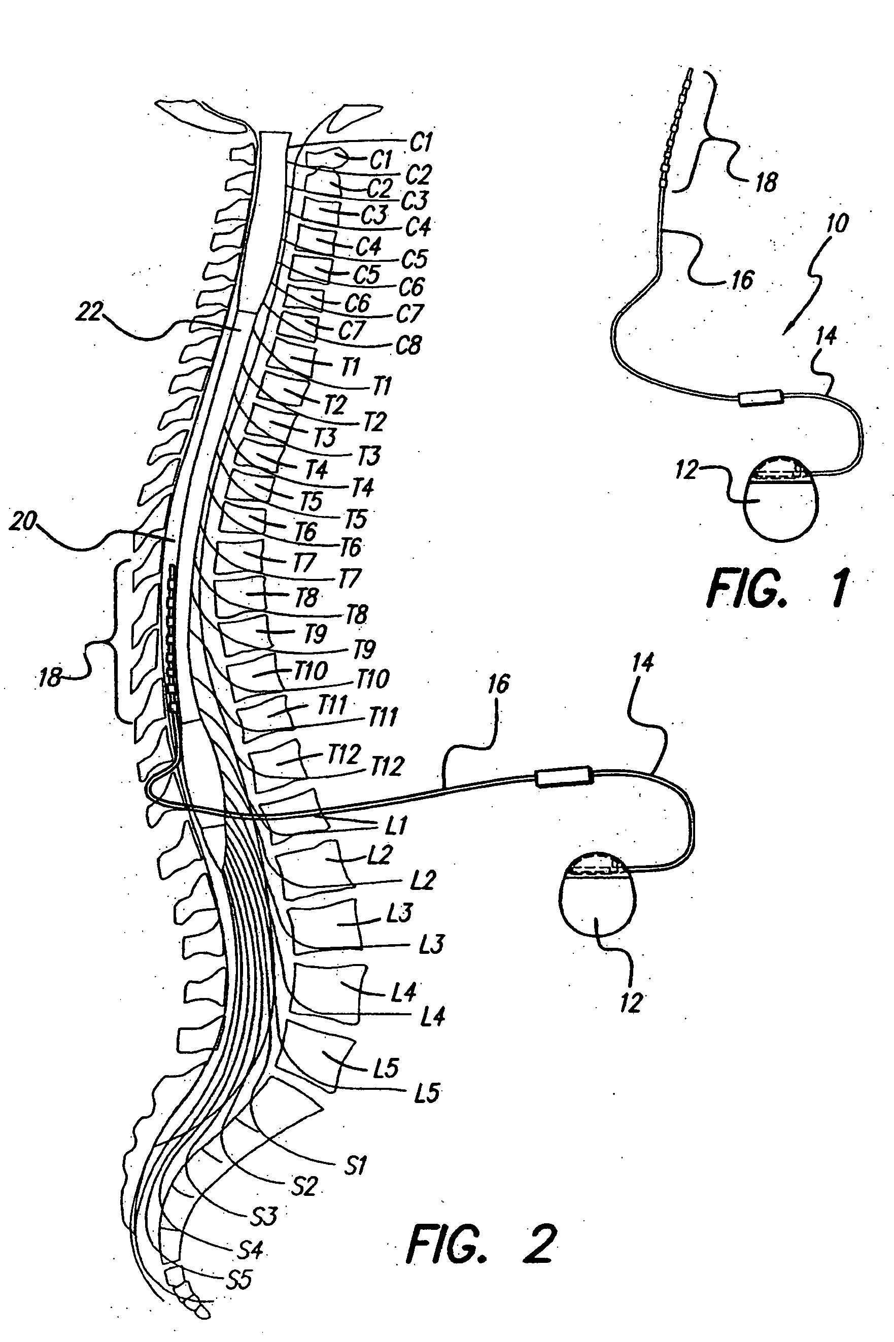
[0021] The at least one implanted lead of the system may be implanted near the patient's spinal column, such as in an SCS system. The programmer may be a separate device or may be incorporated into the pulse generating device. The pulse generating device may be an IPG. The programmer is capable of combing the stimulation combinations into a reduced number of new stimulation combinations during or after the programming of the individual stimulation combinations.

Problems solved by technology

However, applying stimulation pulses to a patient using multiple channels may be an inefficient use of stimulator power supply.
Since more net pulses per second may be delivered by a stimulator using multiple channels, there can be an increased drain on the battery.

Method used


Image

  • Expanding single channel stimulator capability on multi-area stimulation programs
  • Expanding single channel stimulator capability on multi-area stimulation programs
  • Expanding single channel stimulator capability on multi-area stimulation programs

Examples


Embodiment Construction

[0028] It is to be understood that this invention is not limited to the particular devices, compositions, methodologies or protocols described, as these may vary. It is also to be understood that the terminology used in the description is for the purpose of describing the particular versions or embodiments only, and is not intended to limit the scope of the present invention which will be limited only by the appended claims.

[0029] It must also be noted that as used herein and in the appended claims, the singular forms “a”, “an”, and “the” include plural reference unless the context clearly dictates otherwise. Thus, for example, reference to an “electrode” is a reference to one or more electrodes and equivalents thereof known to those skilled in the art, and so forth. Unless defined otherwise, all technical and scientific terms used herein have the same meanings as commonly understood by one of ordinary skill in the art. Although any methods, devices, and materials similar or equiva...


PUM


Abstract

Tissue stimulation systems generally include a pulse generating device for generating electrical stimulation pulses, at least one implanted lead including at least one electrode for delivering the electrical stimulation pulses generated by the pulse generating device, and a programmer capable of communicating with the pulse generating device. In tissue stimulation systems, two or more electrical stimulation combinations may be delivered to a patient simultaneously through a reduced number of channels. Systems and methods described herein may combine the two or more stimulation combinations into a reduced number of new stimulation combinations for delivery of the stimulation combinations over a reduced number of channels.

Description

BACKGROUND OF THE INVENTION [0001] The present invention relates to tissue stimulation systems and more particularly to applying electrical stimulation pulses to a patient through a single channel to treat separate areas of the patient's body. [0002] One example of a stimulation system is a spinal cord stimulation (“SCS”) system. Spinal cord stimulation is a well accepted clinical method for reducing pain in certain populations of patients. An SCS system typically includes an Implantable Pulse Generator (IPG) or a radio-frequency (RF) transmitter and receiver, electrodes, electrode leads, and when necessary, lead extensions. The electrodes are implanted along the dura of the spinal cord, and the IPG or RF transmitter generates electrical pulses that are delivered, through the electrodes, to the dorsal column and dorsal root fibers within the spinal cord. Individual electrodes are arranged in a desired pattern and spacing in order to create an electrode array. Individual wires within...

Claims


Application Information

Patent Timeline
IPC IPC(8): A61N1/36
CPCA61N1/36071
Inventor KOTHANDARAMAN, SRIDHARBRADLEY, KERRY
Owner BOSTON SCI NEUROMODULATION CORP
Learn More