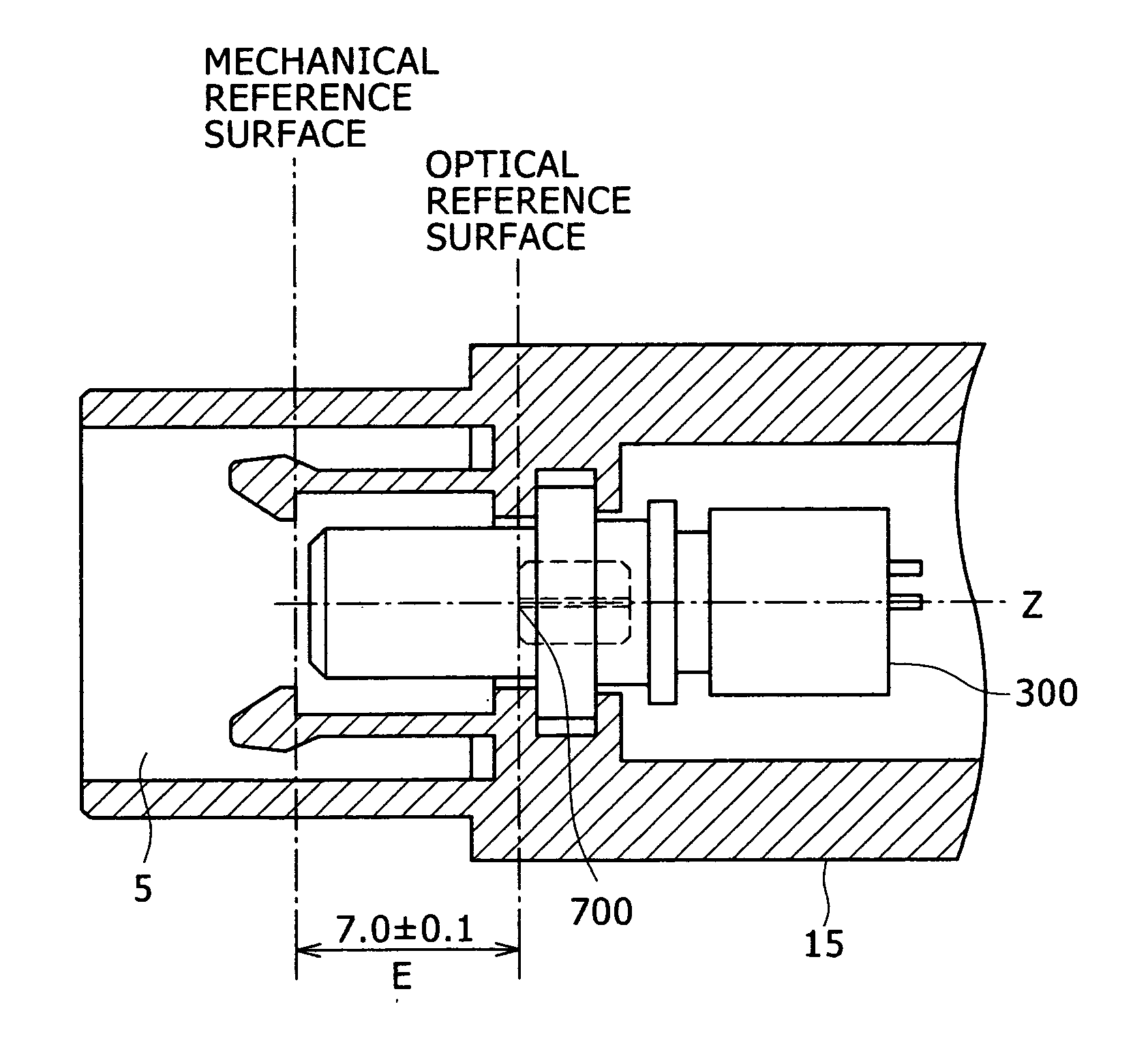
Optical transmission module
a technology of optical transmission module and optical transmitter, applied in the field of optical transmission module, can solve problems such as damage to optical transmitter module or optical receiver module, and achieve the effect of reducing the external influence of tensile for
- Summary
- Abstract
- Description
- Claims
- Application Information
AI Technical Summary
Benefits of technology
Problems solved by technology
Method used
Image
Examples
embodiment 1
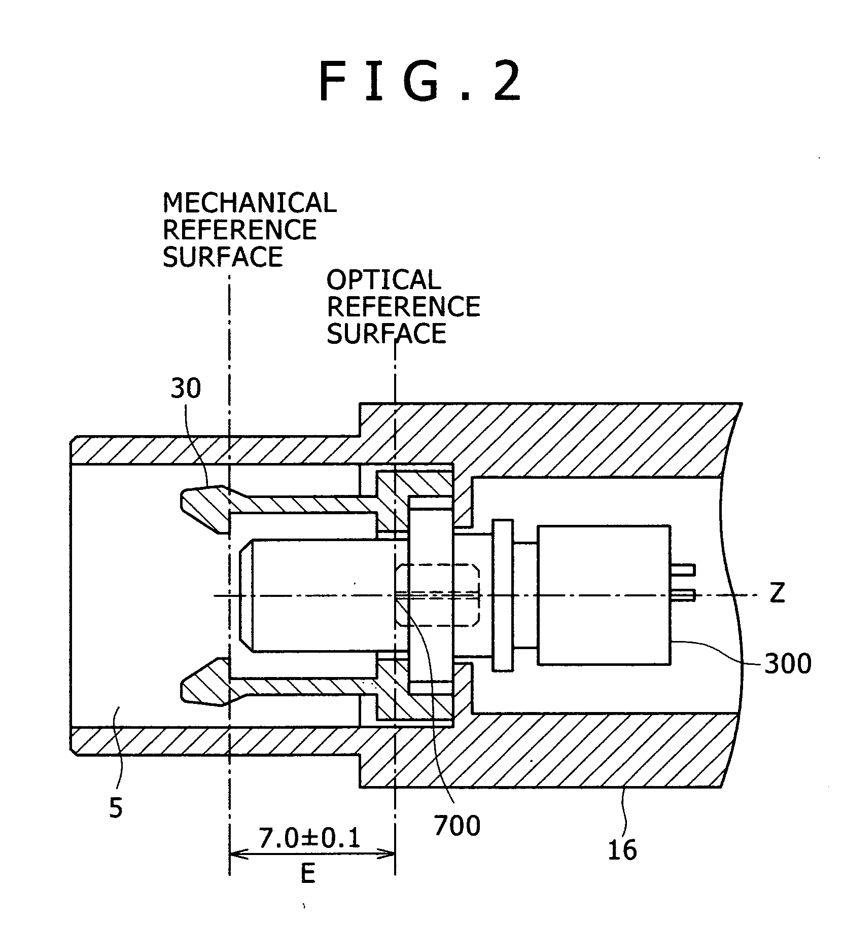
[0039]FIG. 4 is a perspective view illustrating the configuration of an optical transmission module. In FIG. 4, an optical transmission module 1000 is configured to have an optical transmitter module 100, an optical receiver module 200, a printed board 50 in which control circuits for the respective modules 100, 200 are implemented, a receptacle part 5 for connecting an optical transmission plug not shown from the outside of the optical transmission module 1000, and a hook part 30 for holding an optical transmission plug, all of which are stored between an upper case 10 and a lower case 20.
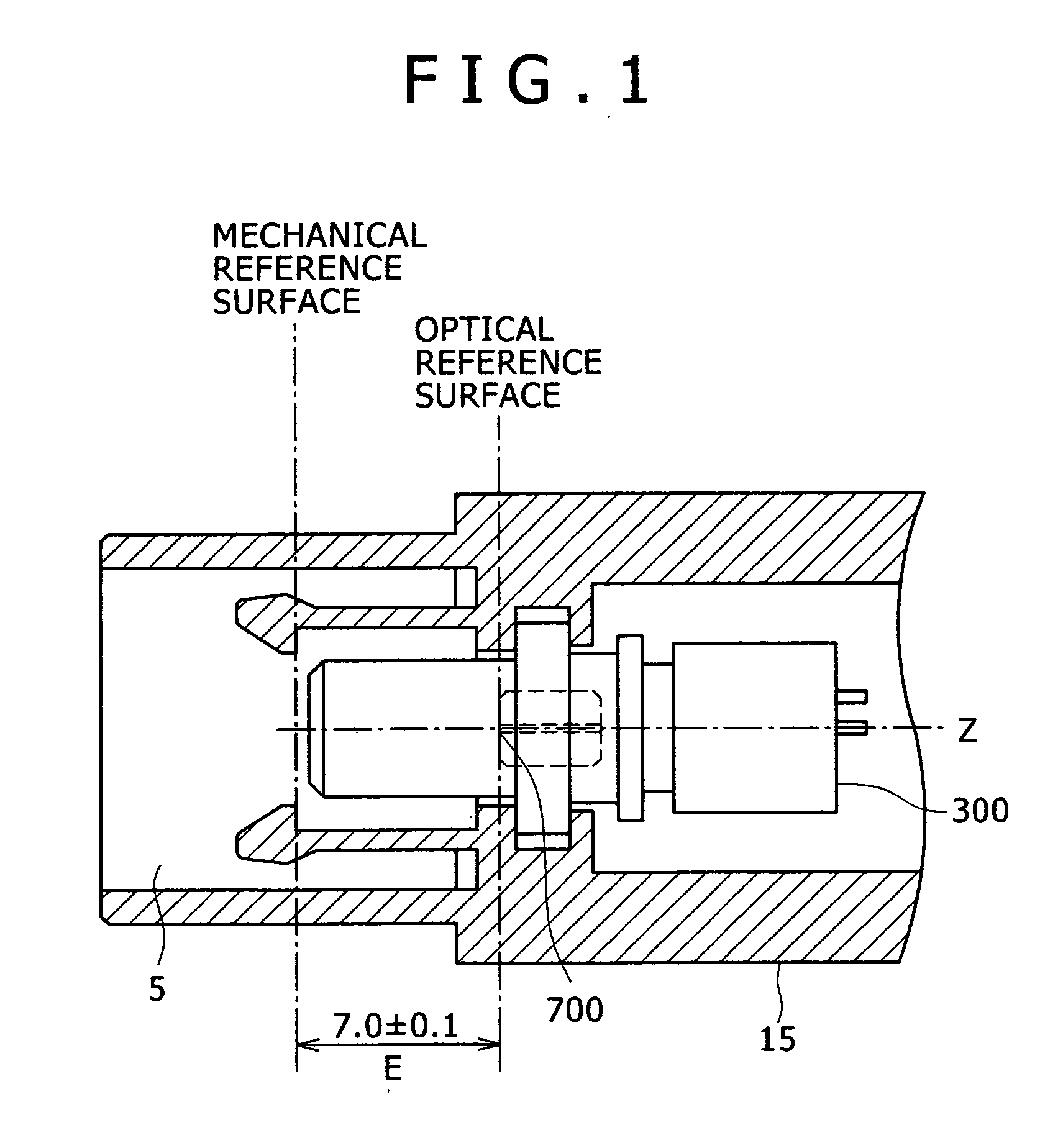
[0040]FIG. 5 is a partial cross-sectional view of the optical communication module case storing the optical communication module which is movable in an optical axis direction. In FIG. 5, the optical communication module 300 is stored in an optical transmission module case 15 having the receptacle part 5 for connecting the optical transmission plug from the outside of the optical transmission modu...
embodiment 2
[0043]FIG. 7 is a partial cross-sectional view of the optical transmission module case storing the optical transmission module which is movable in the X, Y, Z and θxy directions. In FIG. 7, the optical communication module 300 is stored in the optical transmission module case 15 having the receptacle part 5 for connecting the optical transmission plug from the outside of the optical transmission module. The optical communication module 300 and the optical transmission module case 15 have a distance therebetween. Compared with Embodiment 1, the value of the distance DX parallel to the Z-axis is increased and the values of “φR−φA” and “φS−φB” are also increased. As a result, the optical communication module 300 can move in the X and Y directions that are orthogonal to the Z-axis as the optical axis direction, in the Z direction as the optical axis direction and in the θxy direction as the rotation direction. These moving directions of the communication module are closer to the connect...
embodiment 3
[0048]FIG. 11 is a partial cross-sectional view of the optical transmission module case storing the LC connector-type optical communication module which is movable in the Z direction. In FIG. 11, the optical communication module 350 is stored in the optical transmission module case 17 having the receptacle part 7 for connecting the optical transmission plug from the outside of the optical transmission module. The optical communication module 350 and the optical transmission module case 17 have the distance “DX” in parallel to the Z-axis, as well as “φJ350 and between the inner diameters of the transmission module case 17. As a result, the optical communication module 350 can move backward and forward along the Z-axis which is the optical axis direction. When the distance between the optical communication module 350 and the optical transmission module case 17 is “DX”, the distance between the mechanical reference surface and optical coupling surface 750 is “B-DX”.
[0049] According to...
PUM
 Abstract
Description
Claims
Application Information
 - R&D
- Intellectual Property
- Life Sciences
- Materials
- Tech Scout
- Unparalleled Data Quality
- Higher Quality Content
- 60% Fewer Hallucinations
Browse by: Latest US Patents, China's latest patents, Technical Efficacy Thesaurus, Application Domain, Technology Topic, Popular Technical Reports.
© 2025 PatSnap. All rights reserved.Legal|Privacy policy|Modern Slavery Act Transparency Statement|Sitemap|About US| Contact US: help@patsnap.com


