
Mop with Foldaway Rod

a folding rod and mop technology, applied in the field of mop, can solve the problems of increasing the transporting cost accordingly, inconvenient storage, and poor cleaning results, so as to improve the strength of the screw pipe, reduce the transport volume and storage space, and improve the sturdiness of the mop in use.

Inactive Publication Date: 2007-07-05
ZHU ZUELIN
View PDF8 Cites 9 Cited by
  • Summary
  • Abstract
  • Description
  • Claims
  • Application Information

AI Technical Summary

Benefits of technology

[0003] It is therefore an object of the present invention to obviate the disadvantages of prior art mop rod and to provide a kind of mop with foldaway mop rod, which can reduce its transporting volume and storage space.
[0004] A further object of the invention is to provide a kind of mop having relatively large contact area between bottom of the mop head and the ground when being used for cleaning the floor, bringing better cleaning results.
[0009] As the present invention has adopted the above-mentioned technical structure, when using, straighten the upper rod and lower rod of the mop rod, and make the screw sleeve and screw pipe into fixed connection, so as to keep the mop be a tightly connected whole for cleaning use. When the time comes for storage or transport, separate the screw sleeve from the screw pipe, fold the upper rod and lower rod along the connecting rod, in this way, the length of the mop after folding is nearly half of that of the whole mop before folding, which can greatly reduce mop's transport volume and storage space, thus facilitating storage after usage and product transport, with the added advantage of reduction of transport cost. Mounting casing pipe inside the screw pipe can further improve the strength of the screw pipe, as well as the sturdiness of the mop in usage. In addition, with the adoption of universal base structure, the riveting points between upper ends of left and right pull rods and griping handle, the connection points between lower ends of left, right pull rods and the connection block, as well as the connection points between lower ends of left, right support rod and universal base, line together to form a triangle structure. As a result, during actual usage, the mop head can maintain a steady tilt angle, therefore increasing the contact area between the bottom of mop head and the floor, thus effectively improving cleaning results.

Problems solved by technology

However, the longer the mop rod, the larger the volume of the mop, which not only causes inconvenience for storage, and more importantly, also increases its transporting cost accordingly.
In addition, when existing mops are used to clean the floor, the mop head can not maintain a steady tilt angle, the contact area between the bottom of the mop head and the floor is relatively small, therefore its cleaning results are not very satisfactory.

Method used


Image

  • Mop with Foldaway Rod
  • Mop with Foldaway Rod
  • Mop with Foldaway Rod

Examples


Embodiment Construction

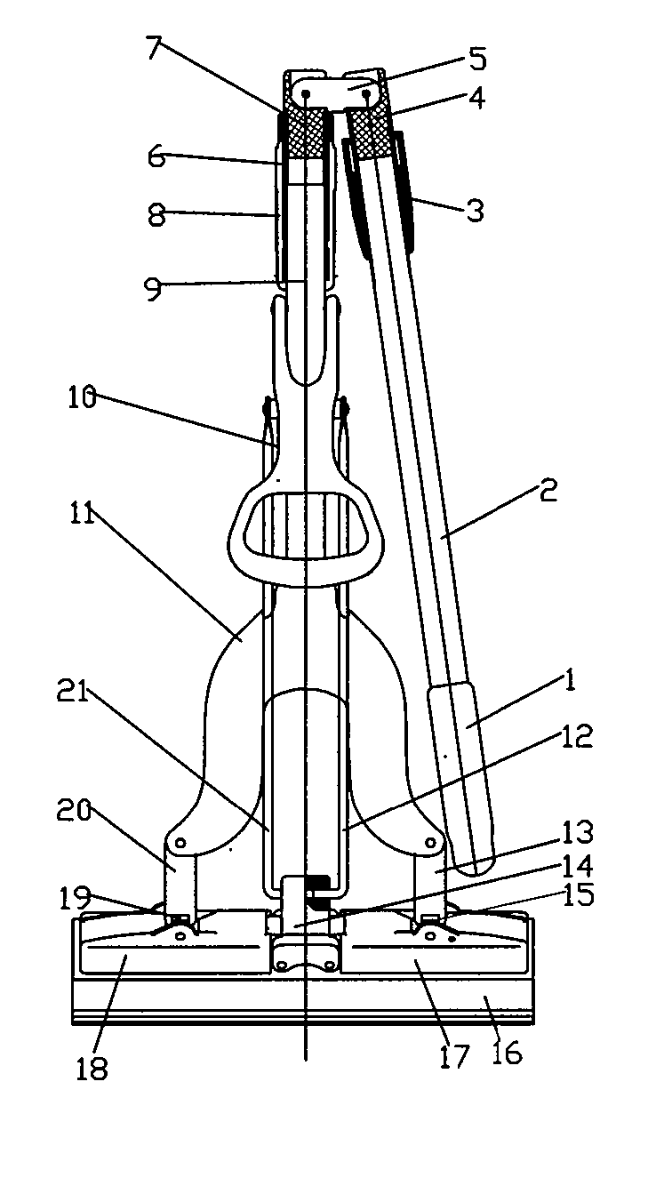
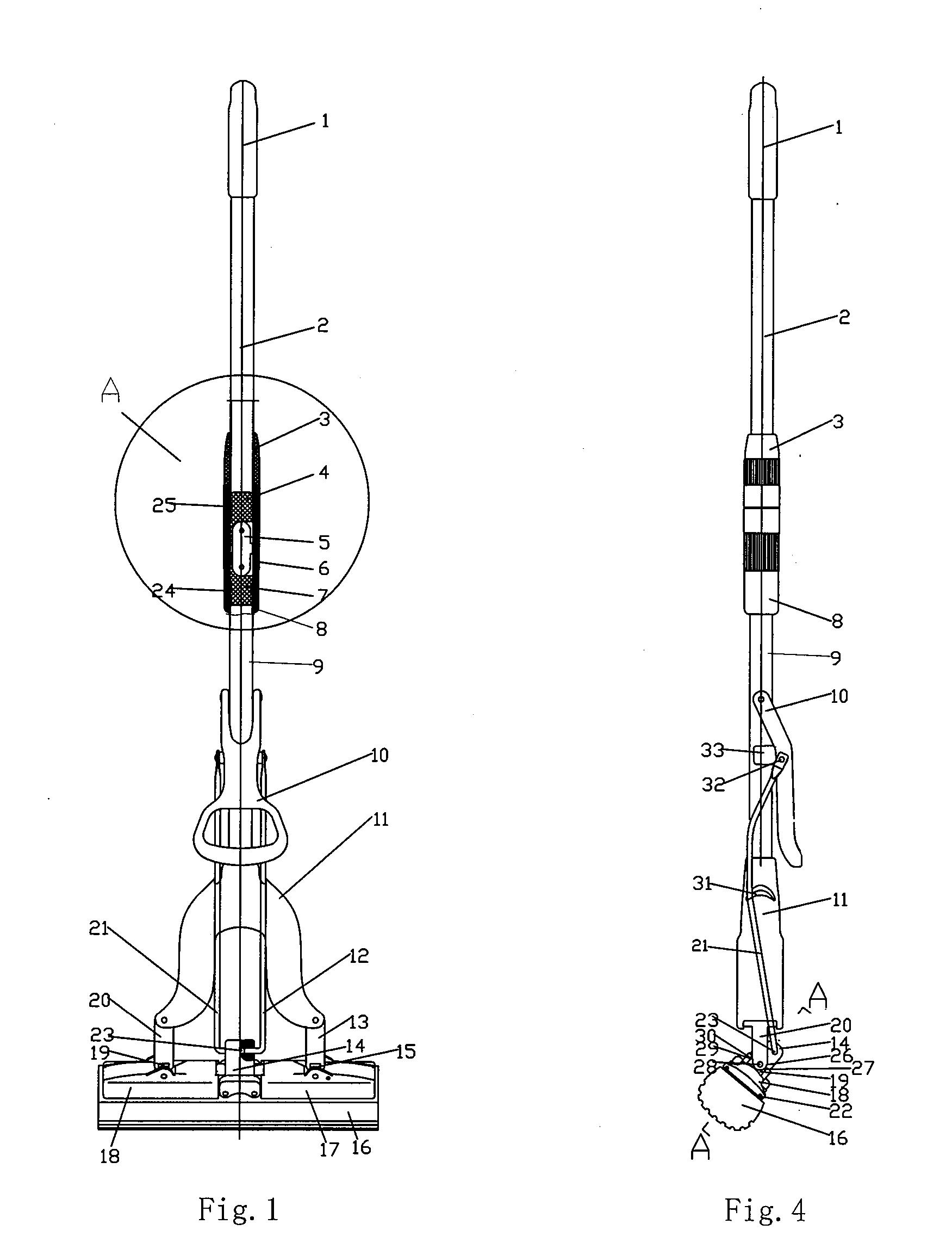
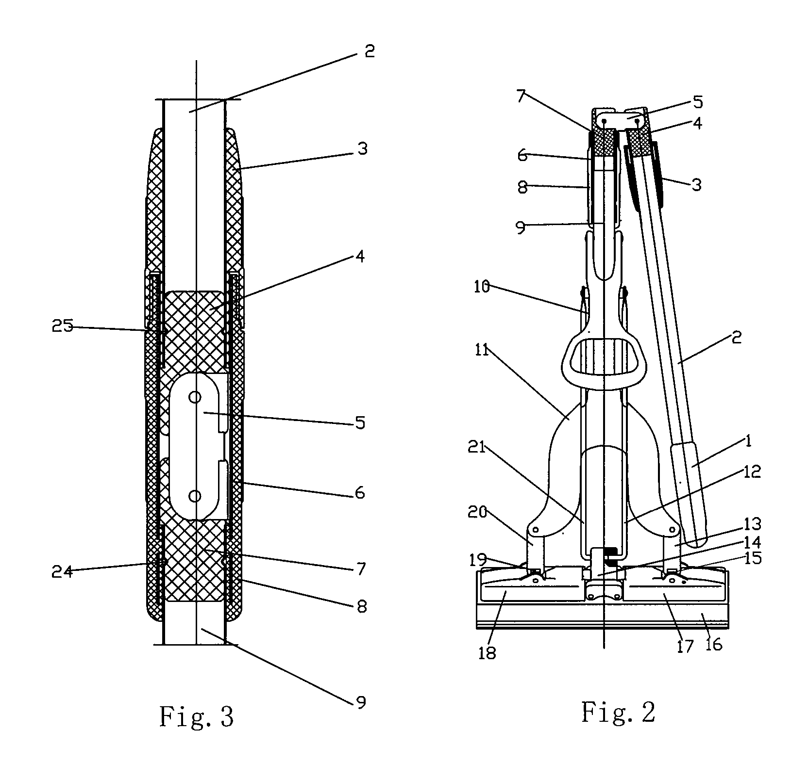
[0018] As shown in FIG. 1 and FIG. 2, a mop includes mop rod, water squeezing mechanism and mop head. Water squeezing mechanism includes hand grip 10, clamping holder base 11, left pull rod 21, right pull rod 12, left support rod 20, right support rod 13, connecting block 14, universal base 15, 19, left base plate 18 and right base plate 17. The mop rod includes upper rod portion, folding mechanism and lower rod 9. Upper rod portion includes upper hand grip 1 and upper rod 2, upper hand grip 1 is riveted onto the upper end of upper rod 2. As shown in FIG. 3, folding mechanism includes screw sleeve 3, upper joint 4, connecting rod 5, casing pipe 6, lower joint 7 and screw pipe 8. Screw sleeve 3 is encased into the bottom of upper rod 2, with which to form tight connection. Upper joint 4 is inserted into the casing at the lower end of upper rod 2, and is firmly connected with upper rod 2 by point riveting. Screw pipe 8 is encased into upper end of the lower rod 9 to form slide fit wit...


PUM


Abstract

The present invention discloses a kind of mop with foldaway mop rod, which includes mop rod, water squeezing mechanism and mop head; the mop rod includes upper rod, folding mechanism and lower rod, the upper and lower ends of folding mechanism are respectively connected with upper rod and lower rod. As the mop rod of the mop can be folded, the transport volume and storage space of which can greatly be reduced, thus facilitating storage after usage and product transport, with the added advantage of reduction of transport cost. In addition, when the mop is being used, the mop head can maintain a steady tilt angle, so as to increase the contact area between the bottom of mop head and the floor, thus effectively improving cleaning results.

Description

FIELD OF THE INVENTION [0001] The present invention relates to a kind of mop. More particularly, the invention provides a mop with foldaway rod. BACKGROUND OF THE INVENTION [0002] Mops are widely used in households, offices, and public areas for cleaning purposes. It is composed of mop rod, water squeezing mechanism and head. When people are using mops, they always wish to have a long mop rod so as to facilitate the cleaning task. However, the longer the mop rod, the larger the volume of the mop, which not only causes inconvenience for storage, and more importantly, also increases its transporting cost accordingly. In addition, when existing mops are used to clean the floor, the mop head can not maintain a steady tilt angle, the contact area between the bottom of the mop head and the floor is relatively small, therefore its cleaning results are not very satisfactory. SUMMARY OF THE INVENTION [0003] It is therefore an object of the present invention to obviate the disadvantages of pr...

Claims


Application Information

Patent Timeline
Patent Type & Authority Applications(United States)
IPC IPC(8): A47L13/146
CPCA47L13/146A47L13/257B25G1/06A47L13/51A47L13/258
Inventor ZHU, XUELINWANG, HAILIN
Owner ZHU ZUELIN
Learn More