
Portable computer with a power control function

a technology of power control and portable computers, applied in the field of portable computers, can solve the problems of obstructing the beauty of the outer appearance of the notebook computer, wasting power supply, and mechanical cover switch malfunction, and achieve the effect of saving the battery power supply of the notebook computer

Active Publication Date: 2007-06-28
ASUSTEK COMPUTER INC
View PDF17 Cites 14 Cited by
  • Summary
  • Abstract
  • Description
  • Claims
  • Application Information

AI Technical Summary

Benefits of technology

[0008]The present invention has been accomplished under the circumstances in view. It is one object of the present invention to provide a portable computer with a power control function, which saves the battery power supply of a notebook computer.
[0009]It is another object of the present invention to provide a portable computer with power control function, which accurately controls the LCD display power supply and system power supply of a notebook computer.

Problems solved by technology

However, the LCD display of the notebook computer may still in action, wasting much power supply.
The use of a cover switch in a notebook computer obstructs the sense of beauty of the notebook computer's outer appearance.
Further, the mechanical cover switch may malfunction when by an external force deforms the LCD display of the notebook computer accidentally.
However, it is difficult to control the generation of the predetermined Gauss value between magnets, and the distance detected by the sensor of the magnetic switch may change.
Further, the Gauss value may attenuate after a long use of the magnetic switch, resulting in a control error.
In this case, the magnetic switch may switch off the power supply of the backlight module of the LCD display erroneously when the notebook computer is kept opened.

Method used


Image

  • Portable computer with a power control function
  • Portable computer with a power control function
  • Portable computer with a power control function

Examples


Embodiment Construction

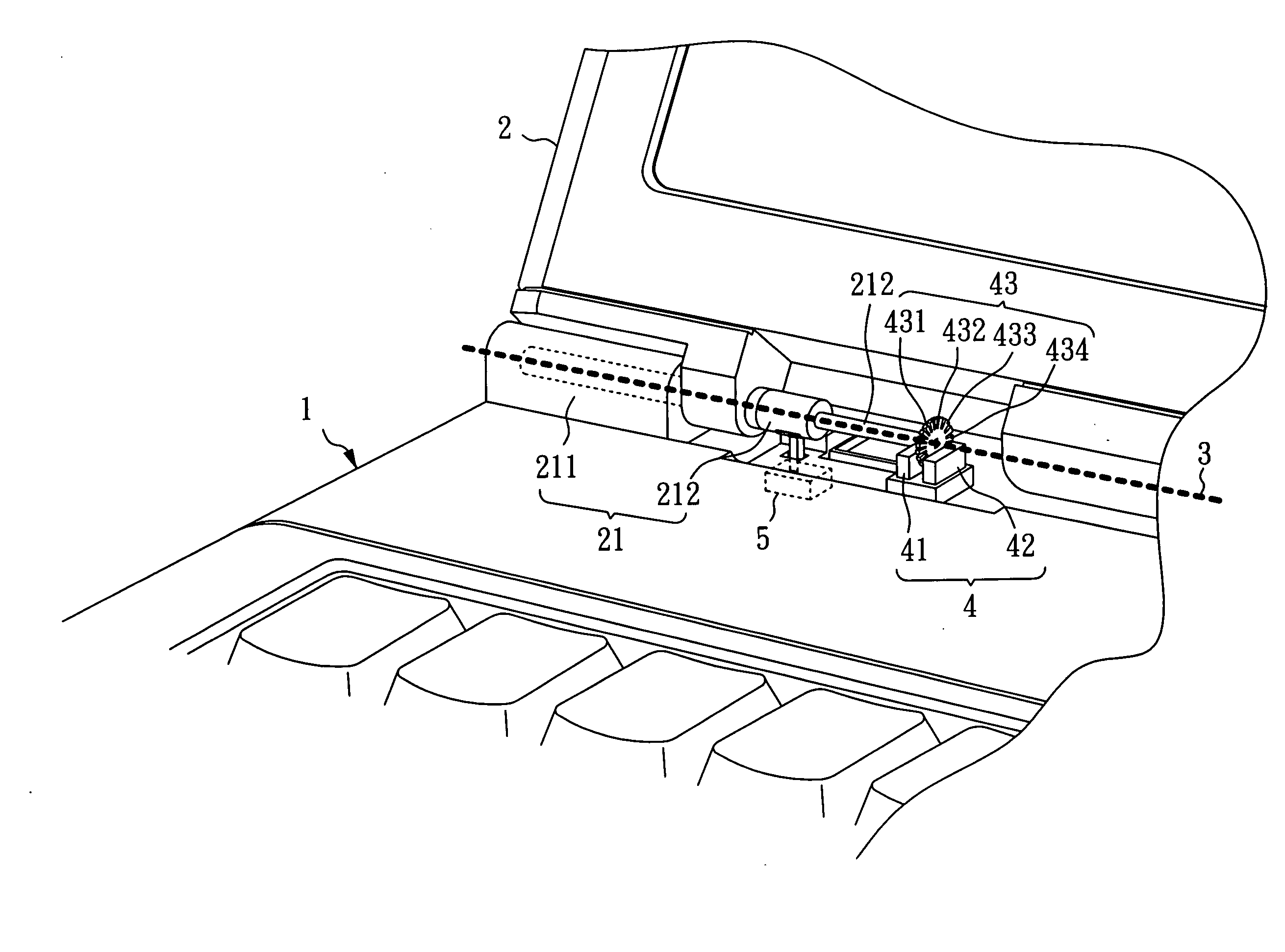
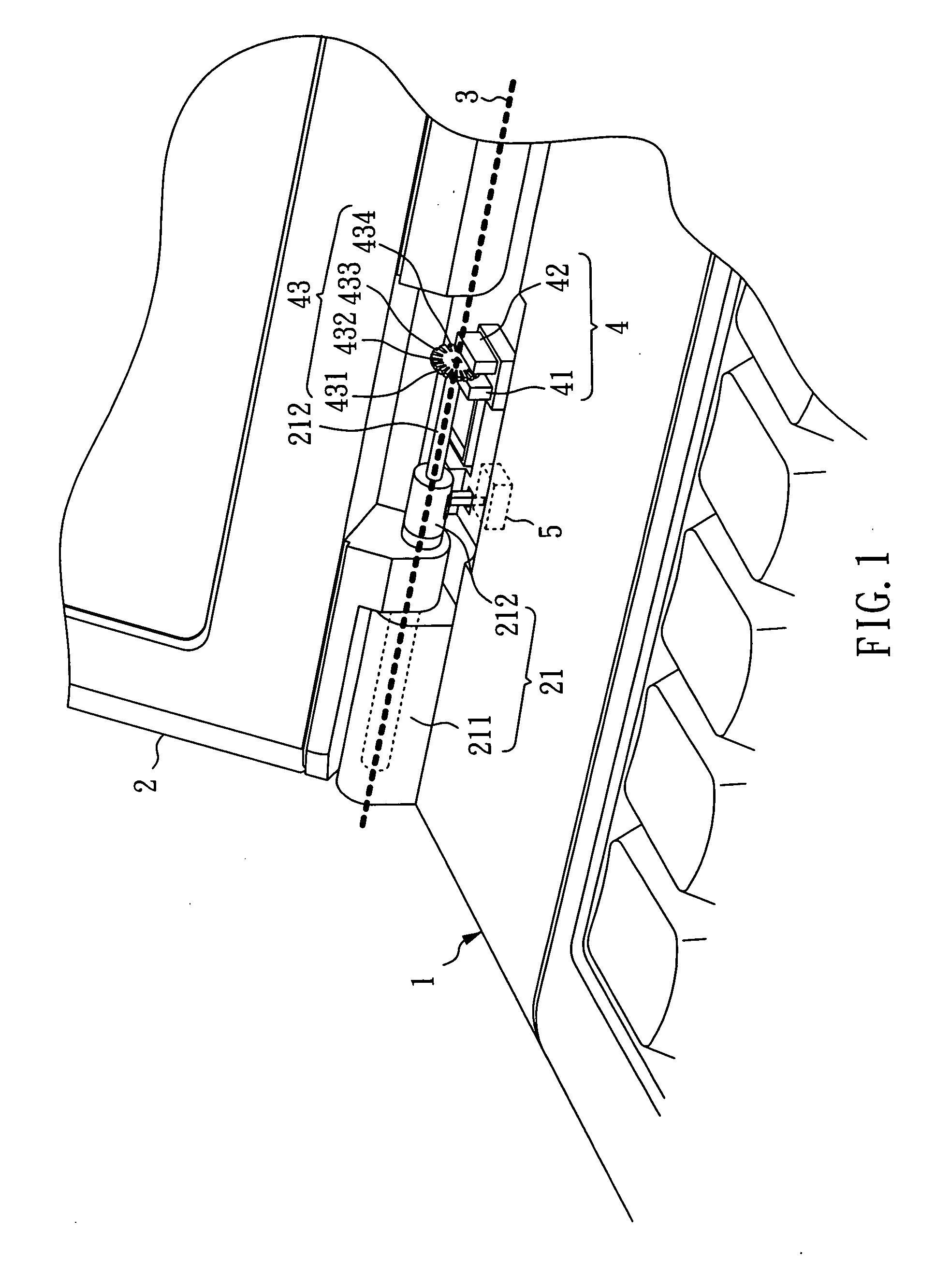
[0023]Referring to FIG. 1, a portable computer with a power control function in accordance with the preferred embodiment of the present invention is shown comprising a first body 1, a second body 2, and a hinge 21. The hinge 21 has a first part 211 and a second part 212. The first part 211 and the second part 212 are pivotally coupled together. The first part 211 is affixed to the first body 1. The second part 212 is affixed to the second body 2 and pivoted to the first part 211. By means of the hinge 21, the first body 1 and the second body 2 are rotatable relative to each other. Further, there is an imaginary axis 3 between the first body 1 and the second body 2 about which the second body 2 is turned relative to the first body 1.

[0024]The portable computer according to the present preferred embodiment is a notebook computer. In other embodiments of the present invention, the portable computer may be any of a variety of portable computers having a display unit, for example, a smar...


PUM


Abstract

A portable computer with a power control function is disclosed to include a first body, a hinge, a second body coupled to the first body through the hinge, an optical sensor having a transmitter and a receiver and mounted on the first body, an optical grating connected to the hinge and having a part located between the transmitter and the receiver, a control circuit, and an electronic component. When the second body is turned relative to the first body, the optical sensor generates a first sensing voltage and a second sensing voltage subject to the turning action of the optical grating so that the control circuit controls the power of the electronic component based on the first sensing voltage and the second sensing voltage provided by the optical sensor.

Description

BACKGROUND OF THE INVENTION[0001]1. Field of the Invention[0002]The present invention relates to a portable computer and, more particularly, to a portable computer with a power control function.[0003]2. Description of Related Art[0004]The management of the power supply of a notebook computer is quite important because notebook computer users are more and more critical on the characteristic of mobility. The power supply of a notebook computer includes two parts, namely, the system power supply for the main unit and the power supply for the LCD display.[0005]In many circumstances, a notebook computer user needs only to use the main unit of the notebook computer without using the LCD display. For example, when making a brief presentation, the user may connect a projector to the notebook computer to display the content of the brief presentation by projection. At this time, the notebook computer operator needs not to use the LCD display of the notebook computer. However, the LCD display ...

Claims


Application Information

Patent Timeline
Patent Type & Authority Applications(United States)
IPC IPC(8): G06F1/00
CPCG06F1/1616G06F1/1677G06F1/1681G06F1/1684
Inventor CHEN, CHIH-PIN
Owner ASUSTEK COMPUTER INC
Learn More