
Work machine with transition region control system

a control system and work machine technology, applied in the direction of applications, instruments, roads, etc., can solve the problems of unnecessarily expensive paving material, inefficient application of paving material with a thickness that deviates from a desired thickness, and exhausted paving material,

Active Publication Date: 2007-06-28
CATERPILLAR INC
View PDF11 Cites 27 Cited by
  • Summary
  • Abstract
  • Description
  • Claims
  • Application Information

AI Technical Summary

Benefits of technology

The present patent is about a system and method for controlling a work machine that is moving over a surface. The system includes sensors that can detect the speed of the work machine, and a controller that can use this information to control the operation of surfacing components that are forming a new surface. This allows for a smooth transition between the two surfaces and ensures that the work machine is always moving at a safe speed. The technical effect of this patent is to improve the efficiency and safety of work machines that are moving over surfaces.

Problems solved by technology

Because paving material can be expensive and is often used in large quantities, applying paving material with a thickness that deviates from a desired thickness can be inefficient.
Paving material applied too thickly may be unnecessarily expensive and exhausted before the roadway surface is complete, and material applied too thinly may result in premature failure of the roadway surface due to reduced load-bearing properties.
Over time an asphalt surface may become misshapen or otherwise unsuitable for vehicular traffic due to various factors, such as, for example, roadway usage, temperature variation, moisture variation, and physical age.
For large worksites, stake placement can be a lengthy and tedious process.
However, the system of the '761 patent defines a surface using a complex set of instructions.
The system of the '761 patent increases the complexity and associated costs of the contouring operation and may be overly complicated for many applications.

Method used


Image

  • Work machine with transition region control system
  • Work machine with transition region control system
  • Work machine with transition region control system

Examples


Embodiment Construction

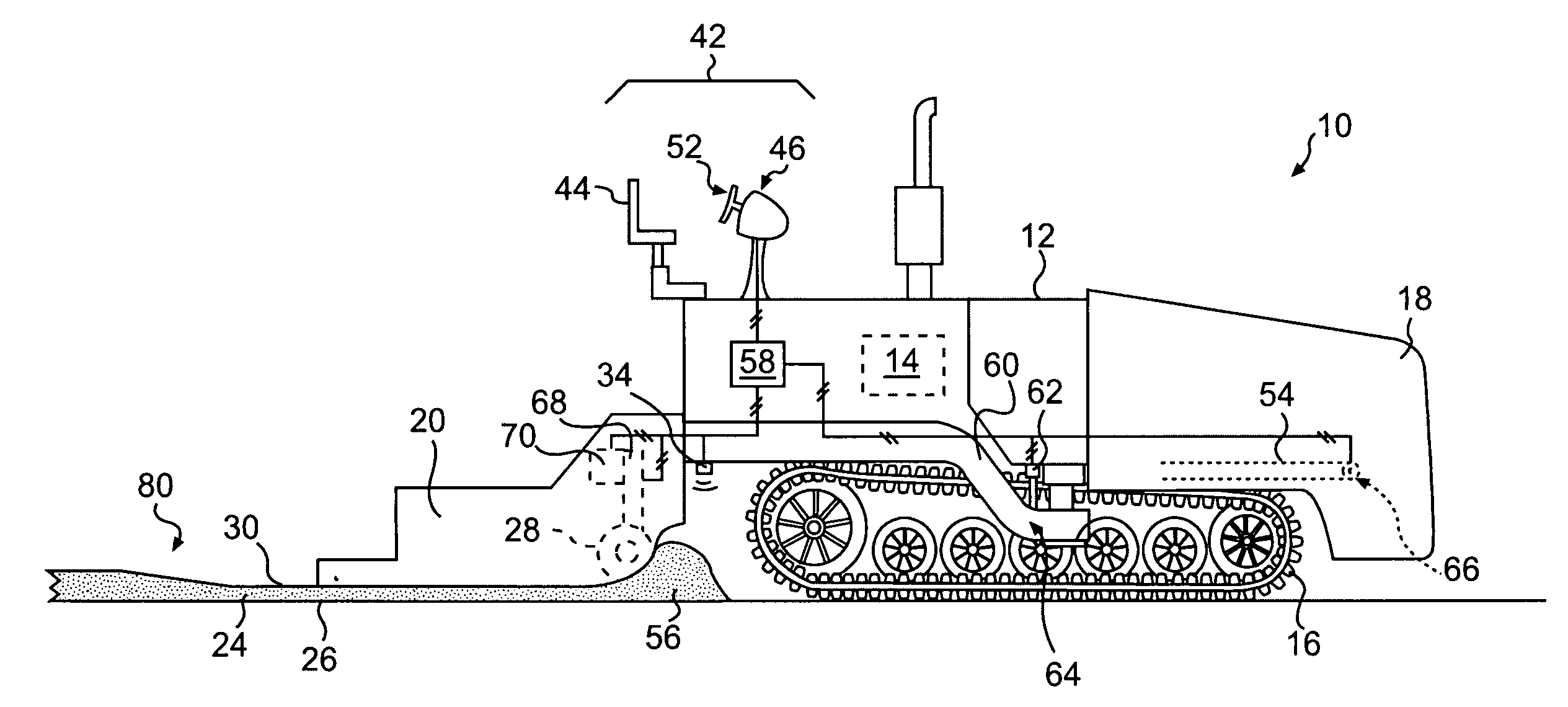
[0016]FIG. 1 is a diagrammatic representation of a work machine 10, according to an exemplary embodiment. Work machine 10 may include a tractor 12, a hopper 18, a screed 20, and a transition region control system (TRCS) 58. In some embodiments, work machine 10 may include an asphalt paver or similar machine configured to add material to a surface 26. Alternatively, work machine 10 may be configured to remove material from surface 26. For example, work machine 10 may include a milling machine or similar device configured to remove asphalt and / or other materials from surface 26. As shown in FIG. 1, work machine 10 may be configured to add a material 24 to surface 26 to form a new surface 30. Material 24 may include asphalt, concrete, loose aggregate materials such as crushed gravel, or any suitable material used to construct roadways, pavements, or other surfaces.

[0017] Tractor 12 may be configured to propel work machine 10. Tractor 12 may include a power source 14, one or more tract...


PUM


Abstract

A transition region control system has one or more sensors configured to transmit a signal representative of a speed of a work machine moving over a first surface. The transition region control system also has one or more surfacing components configured to form a second surface generally coplanar to the first surface, wherein the second surface may include a transition region generally non-coplanar to the first surface. The transition region control system further has a data input system configured to transmit data representative of the transition region to a controller. The controller may be configured to determine the speed of the work machine based on the signal received from the one or more sensors and control the operation of at least one of the one or more surfacing components to at least partially form the transition region based on the speed of the work machine and the data representative of the transition region.

Description

TECHNICAL FIELD [0001] The present disclosure relates to a work machine with a transition region control system, and more particularly, to a work machine with a transition region control system for controlling the formation of a new surface. BACKGROUND [0002] During roadway construction, paving machines may be used to deposit paving material to form a roadway surface. Because paving material can be expensive and is often used in large quantities, applying paving material with a thickness that deviates from a desired thickness can be inefficient. Paving material applied too thickly may be unnecessarily expensive and exhausted before the roadway surface is complete, and material applied too thinly may result in premature failure of the roadway surface due to reduced load-bearing properties. [0003] Roadway construction may also require milling operations to remove roadway material. Over time an asphalt surface may become misshapen or otherwise unsuitable for vehicular traffic due to va...

Claims


Application Information

Patent Timeline
Patent Type & Authority Applications(United States)
IPC IPC(8): G06F19/00
CPCE01C19/004
Inventor RASMUSSEN, TERRY L.
Owner CATERPILLAR INC
Learn More