
Dynamic heart rate monitor

a heart rate monitor and dynamic technology, applied in the field of heart rate monitors, can solve the problems of low accuracy, user discomfort and difficulty in breathing during exercise, and harm in keeping exercise, and achieve the effect of accurately measuring the heart rate of female users

Inactive Publication Date: 2007-06-21
HUNG CHIN YEH
View PDF11 Cites 27 Cited by
  • Summary
  • Abstract
  • Description
  • Claims
  • Application Information

AI Technical Summary

Benefits of technology

"The present invention is a dynamic heart rate monitor that can be comfortably worn on the user's neck and chest to measure the user's heart rate during exercise. The monitor includes two electrodes that are made of conductive rubber vacuum mounts that can be easily attached to the user's chest. The electrodes measure the variation of voltage frequency induced by the user's heart rate, which is then calculated and output through a LCD display. The technical effects of the invention are accurate and comfortable heart rate monitoring during exercise."

Problems solved by technology

It is harmful to keep exercising when the heart rate is at the maximum level.
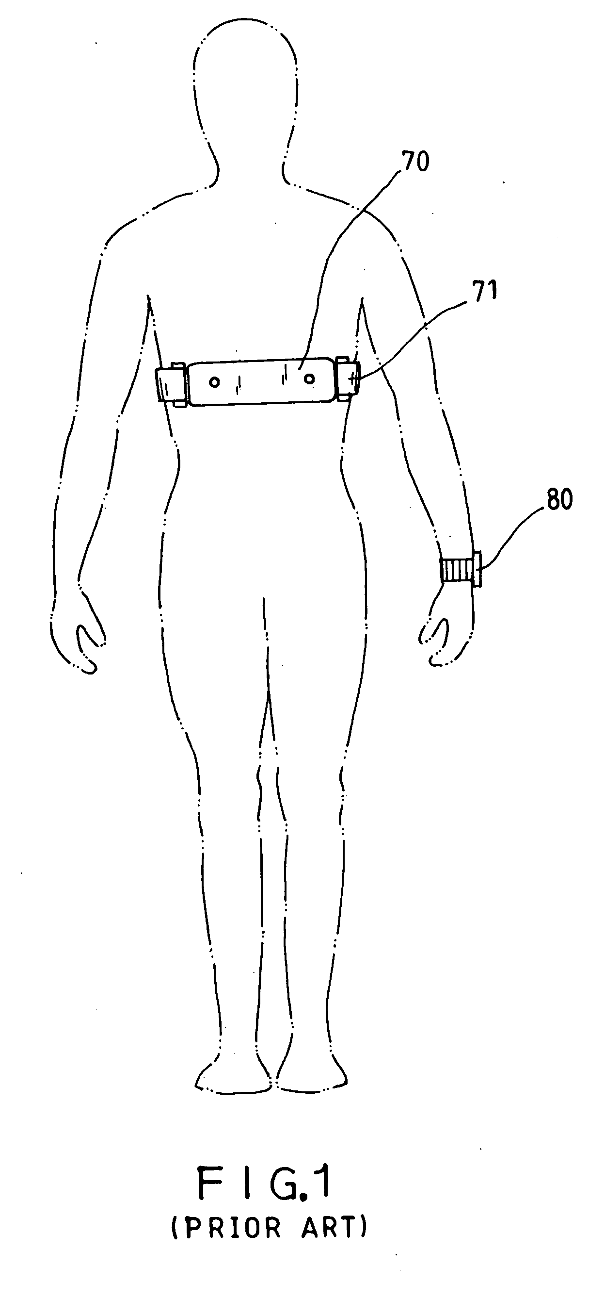
Because electronic device 70 is secured to the user's chest by the belt 71, the binding pressure of the belt 71 causes the user to feel uncomfortable and difficult to breathe during exercise.
Because a male has a big breast profile, it is difficult to keep the electronic device 70 in close contact with the chest to measure the heart rate accurately, resulting in a low accuracy.
When performing a running exercise, the user's hands are alternatively moved forwards and backwards, resulting in an error in the signal transmitted by the electronic device 70 and received by the receiver 80.

Method used


Image

  • Dynamic heart rate monitor
  • Dynamic heart rate monitor
  • Dynamic heart rate monitor

Examples


Embodiment Construction

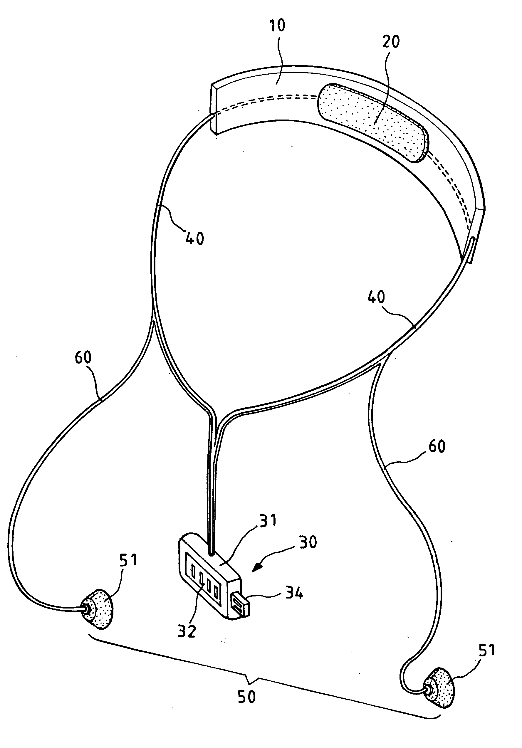
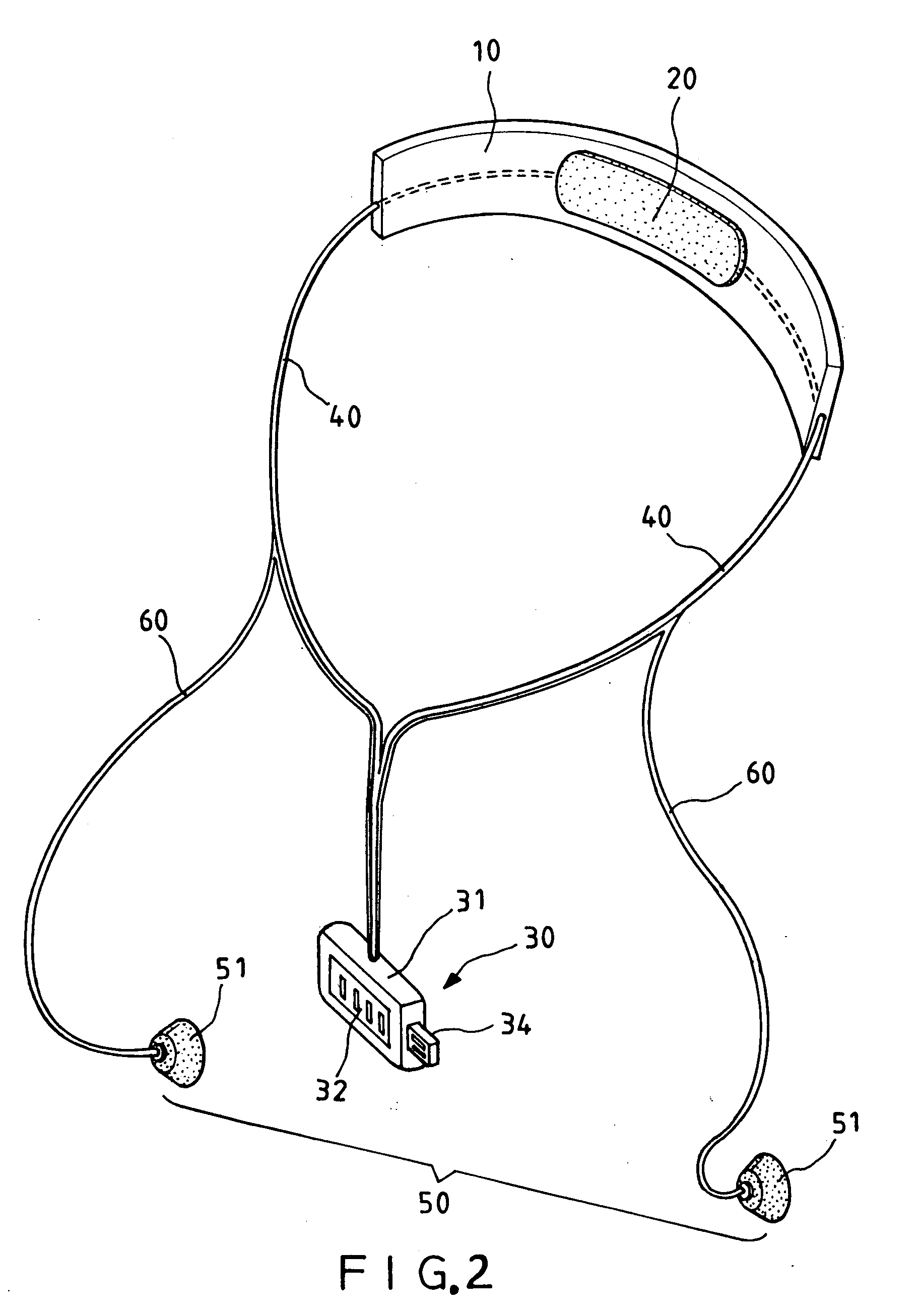
[0018] Referring to FIGS. 2 through 5, a dynamic heart rate monitor in accordance with the present invention is shown comprising a neckband 10, a first electrode set 20, a heart rate recording and display unit 30, a first pair of electric wires 40, a second electrode set 50, and a second pair of electric wires 60.

[0019] The neckband 10 is a smoothly arched band made of elastic or resilient material and can be clamped on the user's neck comfortably without giving much pressure to the user's neck.

[0020] The first electrode set 20 is made out of a conducting rubber or in the form of a conducting pad and mounted in the neck band 10 and curved smoothly outwards from the inner side of the neckband 10 for disposing on the skin of the user's neck closely;

[0021] The heart rate recording and display unit 30, as shown in FIGS. 2 and 5, comprises a casing 31, a LCD (Liquid Crystal Display) 32 mounted in the outside wall of the casing 31, a piezoelectric detection circuit 33 mounted inside th...


PUM


Abstract

A dynamic heart rate monitor is disclosed to include a neckband carrying a first electrode set for disposing on the user's neck, a heart rate recording and display unit, a first pair of electric wires fastened to the neckband and coupled between the first electrode set and the heart rate recording and display unit for suspending the heart rate recording and display unit in front of the user's chest, and a second electrode set form of two electrically conductive rubber vacuum mounts and connected to the heart rate recording and display unit through a second pair of electric wires for attaching to the left and right sides of the user's chest to measure the heart rate and to let the measured heart rate voltage signal to be transmitted to the heart rate recording and display unit for output through a LCD in the heart rate recording and display unit or storage in an external computer via a USB connector at the heart rate recording and display unit.

Description

BACKGROUND OF THE INVENTION [0001] 1. Field of the Invention [0002] The present invention relates generally to a hearty rate monitor and more particularly, to a dynamic heart rate monitor, which is made in the form of a necklace, having two electrically conductive rubber vacuum mounts for attaching to the chest to measure the heart rate. [0003] 2. Description of the Related Art [0004] The heart rate of a person changes significantly before and after exercise. It is important to monitor the change of heart rate during exercise. In order to obtain the maximum benefit from exercise, the pulse of the heart must be kept at about 60% of the maximum pulse rate. It is harmful to keep exercising when the heart rate is at the maximum level. Therefore, using a heart rate monitor that can conveniently and accurately measure the heart rate during exercise is important. [0005] U.S. Pat. No. 6,533,247 discloses an electrode belt of heart rate monitor. According to this design, the electrode belt c...

Claims


Application Information

Patent Timeline
Patent Type & Authority Applications(United States)
IPC IPC(8): A61B5/04
CPCA61B5/02438A61B5/04082A61B5/6822A61B5/6834A61B5/252A61B5/28
Inventor HUNG, CHIN-YEH
Owner HUNG CHIN YEH
Learn More