
A Top Frame for Foldable Tent

a tent and top frame technology, applied in tents/canopies, constructions, building types, etc., can solve the problems of inconvenient open operation of tents, and achieve the effect of convenient open operation and convenient manufacturing and combination features

Inactive Publication Date: 2007-06-14
CHOI KWAN JUN
View PDF10 Cites 9 Cited by
  • Summary
  • Abstract
  • Description
  • Claims
  • Application Information

AI Technical Summary

Benefits of technology

[0009] It is therefore a main object of the present invention to provide a top frame for foldable tent having fewer parts, simple structure, facilitating to manufacturing and combination, easy open operation saving labor features.
[0011] Said spreader has a quad low portion with crossing grooves facilitating to exerting pushing force.
[0012] As utilizing above-mentioned project, due to substituting a hydraulic tappet for the conventional strut, spring and end block and locating device set upon between the static pivot hub and the spreader, the structure has fewer parts, simple, convenient for manufacturing and combination features.
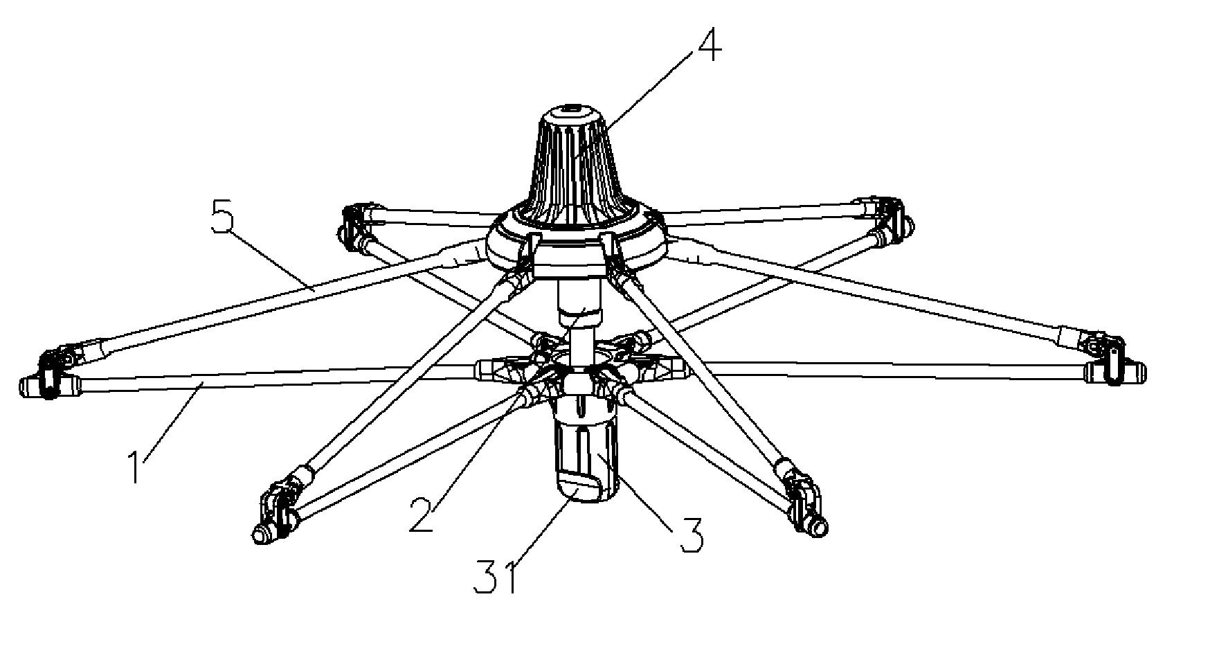
[0013] As in open state, under jack-up and hold-on of said hydraulic tappet, said spreader is pushed down on ultimate low position so that the entire roof braces and sub-braces are kept in open state such as in expending out state; as tending to close the tent, just push up the spreader along the hydraulic tappet to bring the entire roof braces and sub-braces to close to the center downward, by means of tying up of a rope, the tent is closed down; as tending to open the tent, remove away the tying rope, under the pushing function of the hydraulic tappet, the spreader is pushed down to bring the entire roof braces and sub-braces to expend out until get the ultimate point and hold on, so all the open operation is very convenient without any extra force exerting.

Problems solved by technology

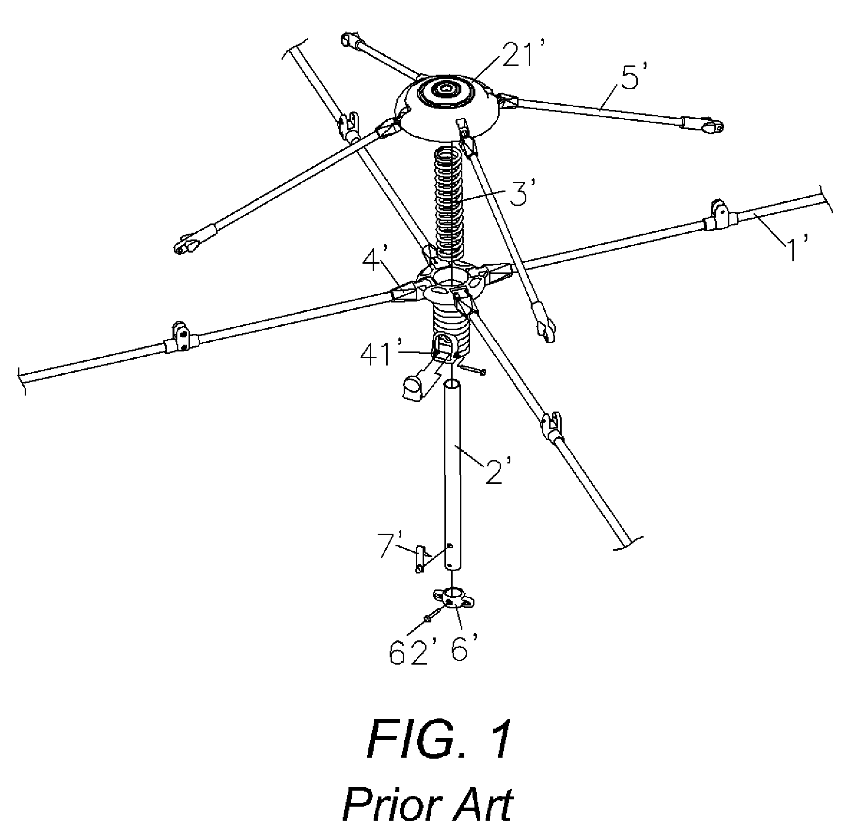
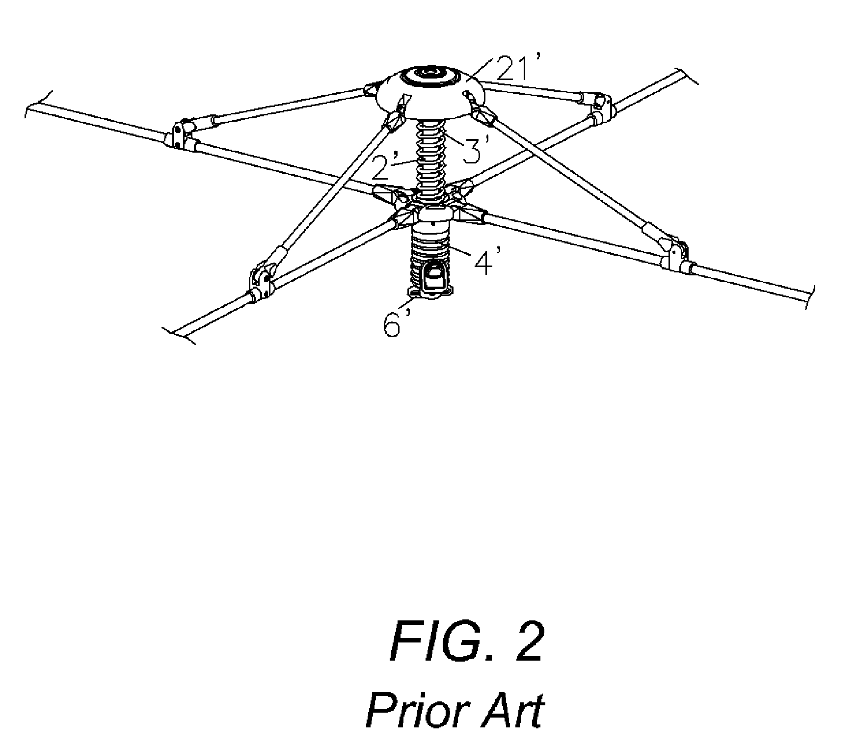
But, the force exerted on the spreader 4′ by the user overcoming the long distance elastic force of the spring 3′ should be enough big, so as to bring inconvenient to the user, especially to the shorter, in order to reach the spreader 4′, they have to stand on tiptoe, even so the spreader 4′ is still not got so that the tent is not able to be opened, hence the open operation the tent is not convenient.

Method used


Image

  • A Top Frame for Foldable Tent
  • A Top Frame for Foldable Tent
  • A Top Frame for Foldable Tent

Examples


Embodiment Construction

[0019] A top frame of foldable tent provided by the present invention is as same as the conventional to suit to foldable tent including a set of foldable roof braces 1 and a set of coordinated sub-braces 5 constructing the main frame.

[0020] Referring to FIG. 3, the present invention is typically comprised of a hydraulic tappet 2 and spreader 3. Wherein said hydraulic tappet 2 is a conventional goods, so the detail is not described here, it typically includes a sleeve 21 and an inner rod 22. One end of the hydraulic tappet 2 (the end of sleeve 21 in drawing) is fixed on the static pivot hub 4 pivoting with the entire sub-braces 5, the another end of the hydraulic tappet 2 (the rod 22 end in drawing) is fixed on the spreader 3, by means of the jack-up and hold-on features of the hydraulic tappet, said spreader 3 is pushed down and kept in the ultimate position to bring the entire roof braces q and sub-braces 5 to expend out.

[0021] As tending to close the tent, just push up the sprea...


PUM


Abstract

The present invention provides a top frame of foldable tent including a set of foldable roof braces and a set of coordinated sub-braces constructing the main frame is typically employed with a hydraulic tappet fixed between the static pivot hub pivoting all the sub-braces and spreader pivoting all the roof braces with both ends, by means of the jack-up and hold-on features of the hydraulic tappet, said spreader is pushed down and kept in the ultimate position to bring the entire roof braces q and sub-braces to expend out. Said structure has fewer parts, simple, convenient for manufacturing and combination features.

Description

BACKGROUND OF THE INVENTION [0001] 1. Field of the Invention [0002] The present invention relates to an attachment for camping and trailering, and more particularly to a lockable top frame for foldable tent. [0003] 2. Description of Prior Art [0004] In accordance with the conventional technology, a top frame for foldable tent, as shown in FIG. 1 and FIG. 2, including a set of foldable roof braces 1′ and a set of coordinated sub-braces 5′ constructing the main frame, is typically comprised of a strut 2′, a spring 3′, a spreader 4′ and an end block 6′, wherein a pivot hub 21′ fixed on the top end of said strut 2′ is pivoted radically and respectively each sub-brace 5′, the another end of said each sub-brace 5′ is pivoted on the foldable roof brace 1; said strut 2′ is put on sequentially with spring 3′ and the spreader 4′ pivoting with all the foldable roof braces 1′ from the bottom end, finally fixed with the end block 6′ via a bowel pin 62′ at the bottom end; approaching the bottom e...

Claims


Application Information

Patent Timeline
Patent Type & Authority Applications(United States)
IPC IPC(8): E04H15/36
CPCE04H15/28
Inventor CHOI, KWAN-JUN
Owner CHOI KWAN JUN
Learn More