
Shoe retention strap

a technology of shoe straps and straps, which is applied in the direction of fastenings, uppers, bootlegs, etc., can solve the problems of compromising the popularity and aesthetic appeal of shoes without heel support, and the availability of additional support, so as to facilitate flexing and movement of the straps, the effect of stabilizing the foot in the sho

Inactive Publication Date: 2007-06-14
TWOMEY DONNA G
View PDF22 Cites 16 Cited by
  • Summary
  • Abstract
  • Description
  • Claims
  • Application Information

AI Technical Summary

Benefits of technology

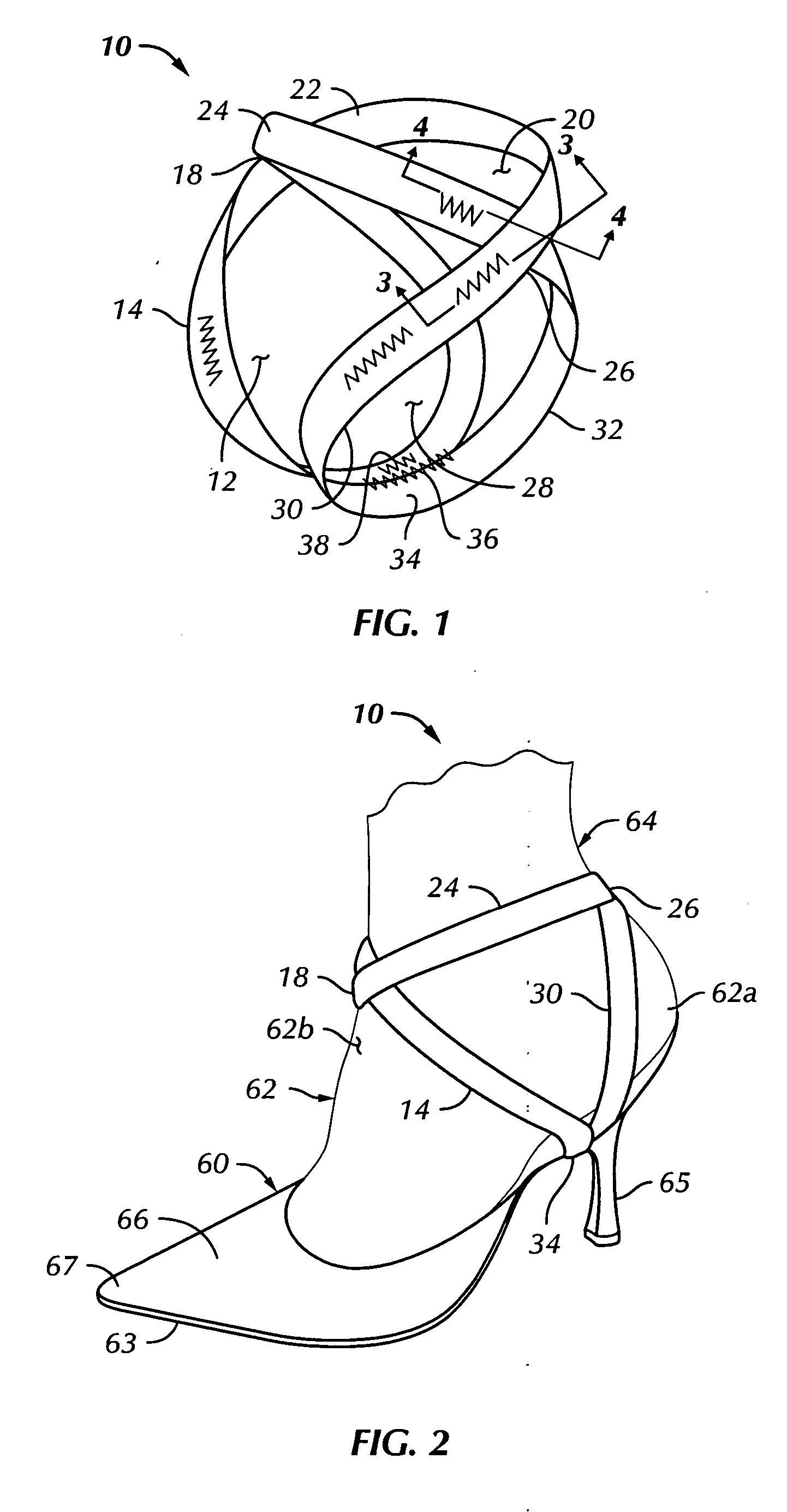
[0004] In accordance with one aspect of the present invention, a strap-like device is provided to stabilize a person's foot in a shoe and to retain the foot firmly in contact with the shoe. The strap device is detachable and interchangeable and may be worn with virtually any shoe without upper structure at the heel portion of the shoe and without altering the design or structure of the shoe itself.
[0005] The shoe retention strap device of the invention further benefits the user or wearer in that the device prevents the heel portion of the foot from lifting away from the insole of the shoe as the wearer walks. The shoe retention strap also prevents trousers from being caught between the foot and the heel portion of the shoe as a person walks in shoes of the general type described herein. Additional benefits provided by the invention include stability of the foot in the shoe when walking in strapless or backless shoes as well as providing stability when a person wearing such types of shoes is driving a motor vehicle, for example.
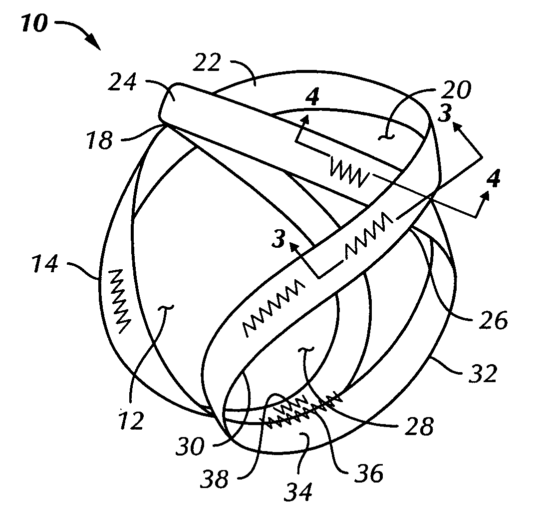
[0006] Still further, the shoe retention strap device of the invention is preferably provided as a continuous strap which may be formed of a resilient or elastic material and is provided with, essentially, three closed loops for retaining the foot firmly attached to the shoe at the heel portion of the shoe. The strap is formed with two opposed coupling portions which provide for retaining the strap loops properly positioned while allowing flexing and movement of the strap while in use to prevent discomfort or injury to the foot.

Problems solved by technology

Heretofore, such additional support has not been available and the popularity and aesthetic appeal of shoes that have no support for the heel has been compromised.

Method used


Image

  • Shoe retention strap
  • Shoe retention strap
  • Shoe retention strap

Examples


Embodiment Construction

[0017] In the description which follows, like parts are marked throughout the specification and drawing with the same reference numerals, respectively. The drawing figures are not necessarily to scale and certain features may be shown exaggerated in scale or in somewhat generalized or schematic form in the interest of clarity and conciseness.

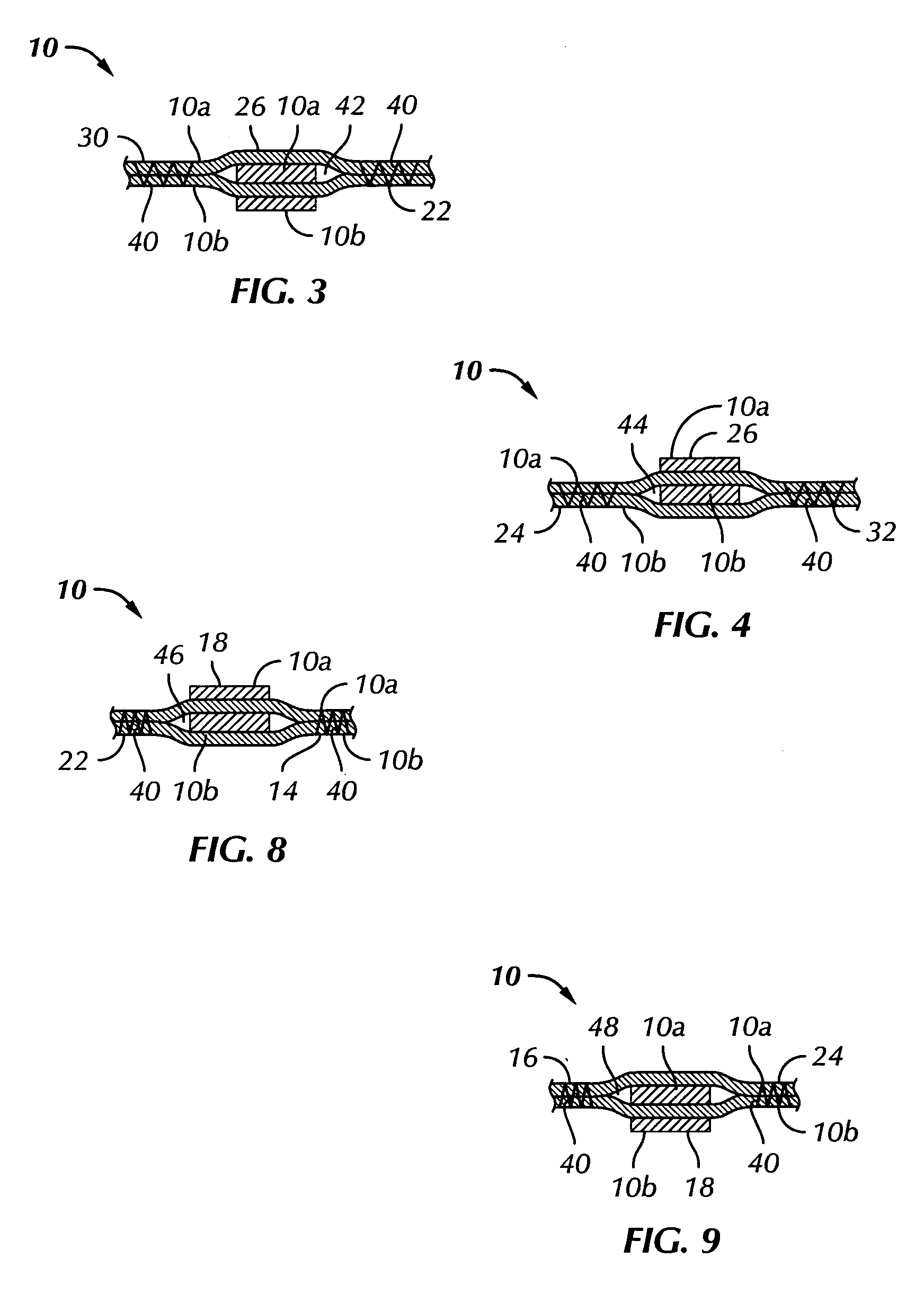
[0018] Referring to FIG. 1, there is illustrated a shoe retention strap device in accordance with the invention and generally designated by the numeral 10. The strap device 10 may take various forms but, preferably, comprises a continuous elongated strap formed of a resilient or elastic material such as braided elastic strapping. Strap device 10 is formed with a first closed loop portion 12 formed by opposed strap segments 14 and 16 which cross at a first coupling 18, see FIG. 6 also, a second closed loop portion 20, FIG. 1, provided by strap segments 22 and 24 which cross at a coupling 26, FIG. 1 and FIG. 5, and a third closed loop portion 28 ...


PUM


Abstract

A shoe retention strap device, particularly adapted for use with shoes without upper structure at the heel portion of the shoe, comprises an elongated elastic strap formed in three loop portions, opposed coupling portions and a bottom part which may be slipped over the shoe and retained engaged with the outsole just forward of the heel. A person's foot may be placed through the loop portions and into the shoe whereby forward and aft loop portions engage the foot and the heel portion of the foot and a third loop portion engages the ankle.

Description

CROSS-REFERENCE TO RELATED APPLICATION [0001] This application claims the benefit of U.S. Provisional Patent Application Ser. No. U.S. 60 / 749,543, filed Dec. 12, 2005.BACKGROUND OF THE INVENTION [0002] Many shoe styles are configured such that there is no support for the heel portion of the foot with respect to keeping the shoe snuggly attached to the foot. Shoe styles known as slides or mules, for example, do not have a vamp portion or other support at the heel of the shoe to assist in retaining the shoe secured to the foot. Although these shoe styles are popular, persons wearing such types of shoe eventually realize that further support is desirable or necessary. Heretofore, such additional support has not been available and the popularity and aesthetic appeal of shoes that have no support for the heel has been compromised. However, the present invention overcomes the disadvantages of the type of shoe described hereinabove and provides a functional as well as aesthetically pleasin...

Claims


Application Information

Patent Timeline
IPC IPC(8): A43C11/00A43B7/20A43B23/00
CPCA43B3/16A43B7/20A43C11/14
Inventor TWOMEY, DONNA G.
Owner TWOMEY DONNA G
Learn More