Method of focus error signal adjustment in optical disk device and optical disk device

a technology of optical disk and focus error signal, which is applied in the direction of data recording, instruments, information storage, etc., can solve the problems of unable to enable the formation of waveform, the error in the waveform of the focus error signal due to the emboss pit, etc., and achieve the effect of accurate focus servo

Inactive Publication Date: 2007-06-07
FUNAI ELECTRIC CO LTD
View PDF3 Cites 2 Cited by
  • Summary
  • Abstract
  • Description
  • Claims
  • Application Information

AI Technical Summary

Benefits of technology

[0008] The present invention is to solve the problem of the conventional art described above, and an object of the present invention is to provide a method of a focus error signal adjustment in an optical disk device which enables an accurate focus servo on the basis of a focus error signal whose amplitude is adjusted and waveform is shaped.

Problems solved by technology

However, a technique described in the Patent Publication No. 2001-222826 cannot prevent a problem that when the emboss pit to which a CAPA (Complementary Allocated Pit Address) is allocated is in a land track and a groove track in the optical disk, an error occurs in the waveform of the focus error signal due to the emboss pit.
Also, a technique described in the Patent Publication No. 2003-233915 cannot enable a formation of the waveform by increasing and decreasing an amplitude of the focus error signal and by making the waveform of the focus error signal be symmetrical with respect to a reference point.

Method used


Image

  • Method of focus error signal adjustment in optical disk device and optical disk device
  • Method of focus error signal adjustment in optical disk device and optical disk device
  • Method of focus error signal adjustment in optical disk device and optical disk device

Examples


Embodiment Construction

[0025] A method of a focus error signal adjustment in an optical disk device according to a preferred embodiment of the present invention is described with reference to FIGS. 1 to 7. The optical disk device of the present preferred embodiment is composed of an optical disk recording device 1. An optical disk of the present preferred embodiment is composed of a DVD-RAM (DVD Random Access Memory).

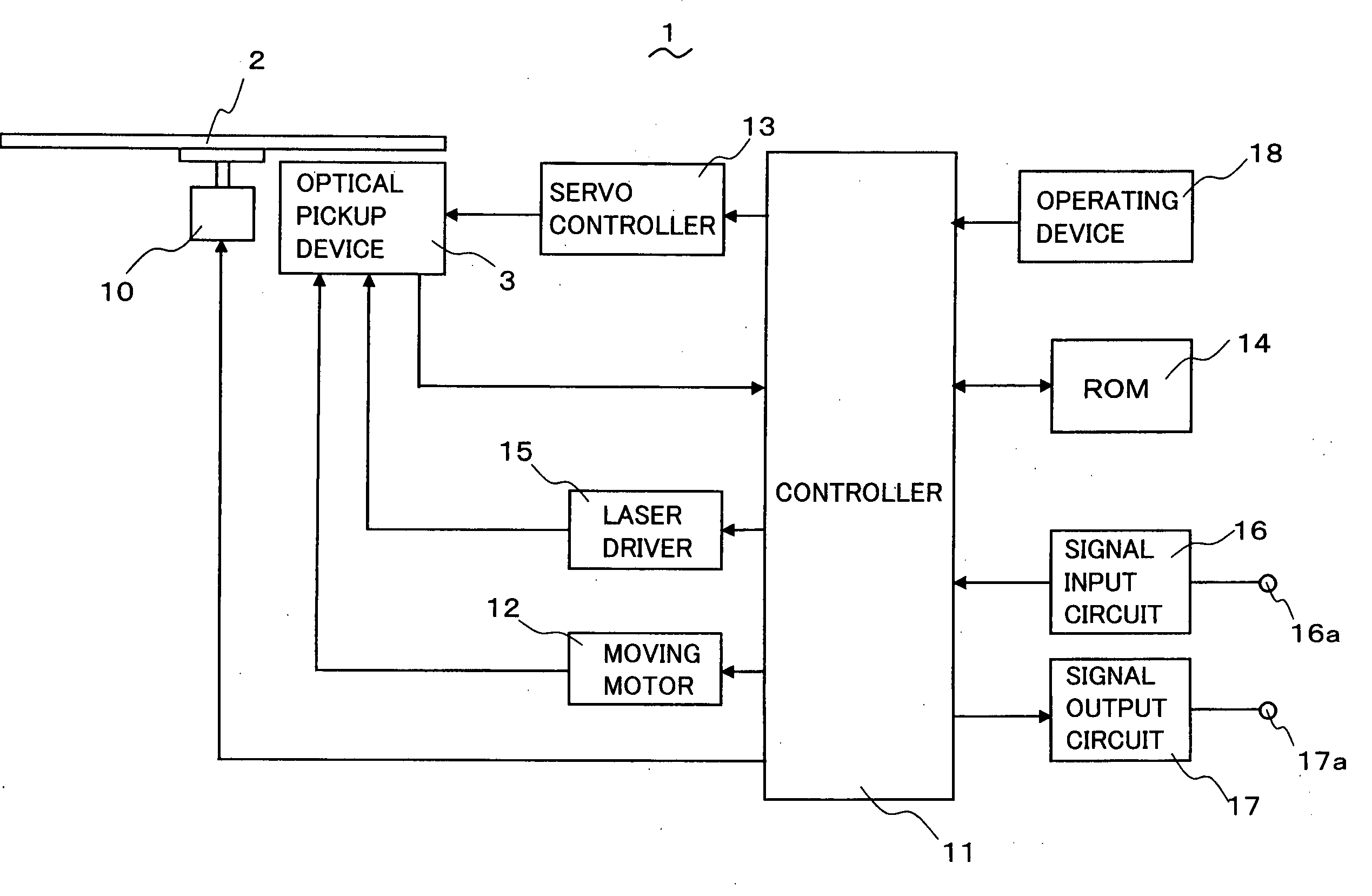
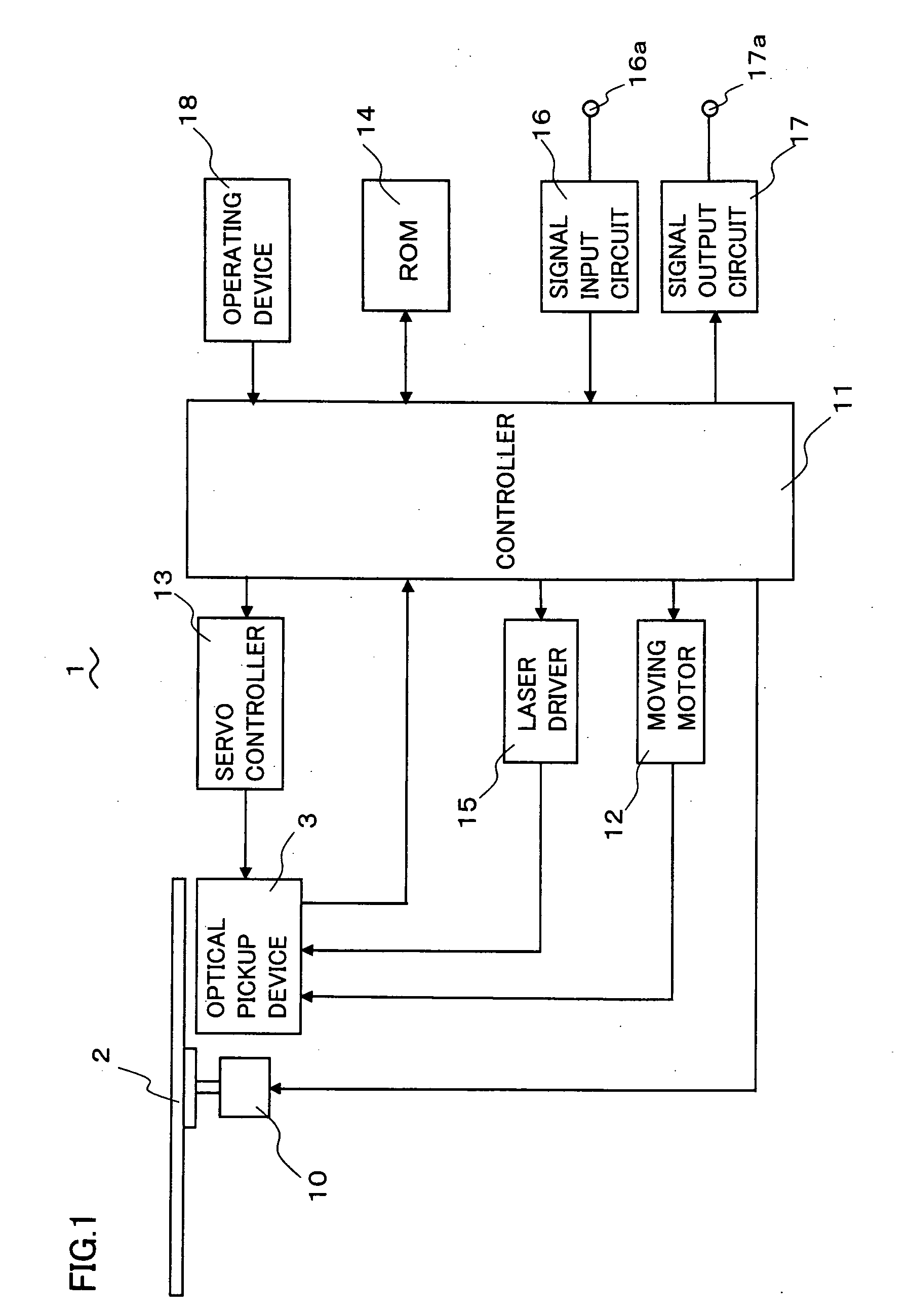
[0026]FIG. 1 shows a composition of an optical disk recording device in which an optical pickup device is installed. The optical disk recording device 1 comprises an optical pickup device 3 which records a data on an optical disk 2 and reads in a data from the optical disk 2, a controller 11 which is composed of a control circuit such as a CPU (Central Processing Unit) or the like, and an operating device 18 which is operated by a user to provide an instruction to the controller 11. The optical disk recording device 1 is a DVD recorder or a DVD drive installed in a personal computer, for exa...


PUM

PropertyMeasurementUnit
compositionaaaaaaaaaa
structureaaaaaaaaaa
distanceaaaaaaaaaa

Abstract

A method for a focus error signal adjustment in an optical disk device which shapes a focus error signal and enables a high-accuracy focus servo is provided. In a DVD-RAM having an emboss data zone and a rewritable data zone, a focus error signal is generated with the DVD-RAM remaining still in a position where an emboss pit is not formed in the rewritable data zone, and a waveform of the FE signal is shaped so that the waveform is symmetrical with respect to a reference point. Then, the FE signal is generated in the emboss data zone and an amplitude of the FE signal is adjusted. The amplitude of the signal which is obtained by increasing the the amplitude of the FE signal whose amplitude is adjusted by approximately 6 dB is applied to the amplitude of the focus error signal in the rewritable data zone. Consequently, a high-accuracy focus servo based on the FE signal, whose amplitude is adjusted and waveform is shaped, can be achieved without an error caused by the emboss pit.

Description

BACKGROUND OF THE INVENTION [0001] 1. Field of the Invention [0002] The present invention relates to a method of a focus error signal adjustment in an optical disk device, which shapes a S-shaped focus error signal used for carrying out a focus servo and which adjusts an amplitude and S-shaped balance of the signal, and the optical disk device thereof. [0003] 2. Description of the Related Art [0004] Conventionally, in an optical disk device, a focus error signal is generated, on the basis of a laser beam reflected on a data recording layer, by irradiating the laser beam on the data recording layer of the optical disk. Here, the focus error signal is a signal obtained by changing a focus position of the laser beam. When generating the focus error signal, the focus servo is carried out on the basis of the signal. The focus servo enables the focus to be in an appropriate position on the optical disk, and then enables an accurate reading and recording of a data. Thus, a regular waveform...

Claims


Application Information

Patent Timeline
Patent Type & Authority Applications(United States)
IPC IPC(8): G11B7/00
CPCG11B7/0908G11B7/0941G11B7/0945
Inventor MITSUDA, HIROSHI
Owner FUNAI ELECTRIC CO LTD
Why Eureka
Try Eureka