Speaker apparatus

a technology of speaker and insulating rod, which is applied in the direction of electrical transducers, transducer details, electrical apparatus, etc., can solve the problems that the efficiency of the magnetic circuit by mounting the repulsive magnet cannot be sufficiently increased, the outer diameter of the repulsive magnet mounted on the pole piece needs to be reduced, and the efficiency of the magnetic circuit cannot be increased sufficiently. achieve the effect of reducing the leakage magnetic flux, reducing the magnetic distortion, and increasing the efficiency of the magnetic circui

Inactive Publication Date: 2007-05-31
PIONEER CORP +1
View PDF1 Cites 9 Cited by
  • Summary
  • Abstract
  • Description
  • Claims
  • Application Information

AI Technical Summary

Benefits of technology

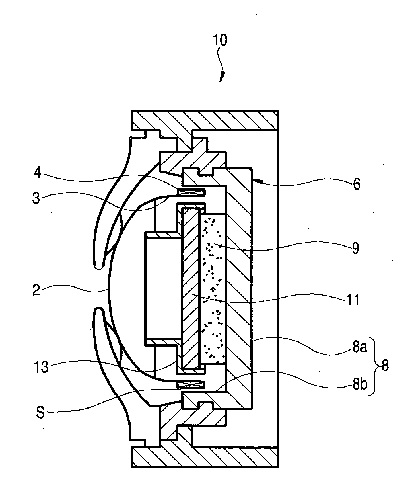
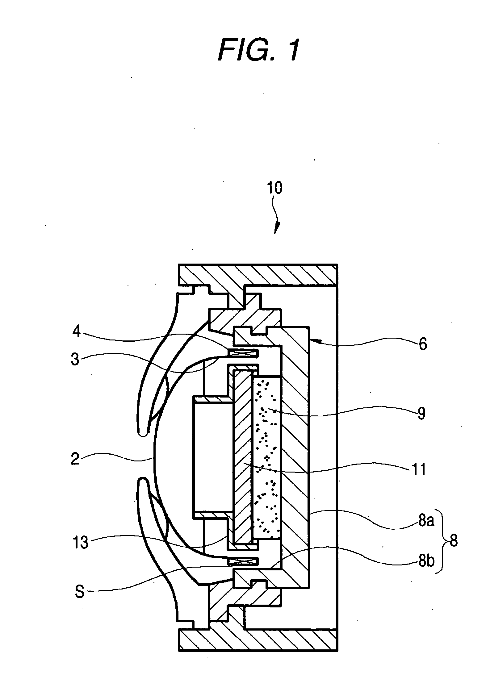
[0014] In the inner magnet type magnetic circuit, it is conceivable to mount the repulsive magnet described in JP-A-2002-78081 in addition to mounting the short-circuit ring described in JP-A-2003-199189 so as to increase the efficiency of the magnetic circuit not only by reducing the magnetic distortion by the nonlinearlity of the permeability but also reducing the leakage magnetic flux to the side of the vibrating plate.

Problems solved by technology

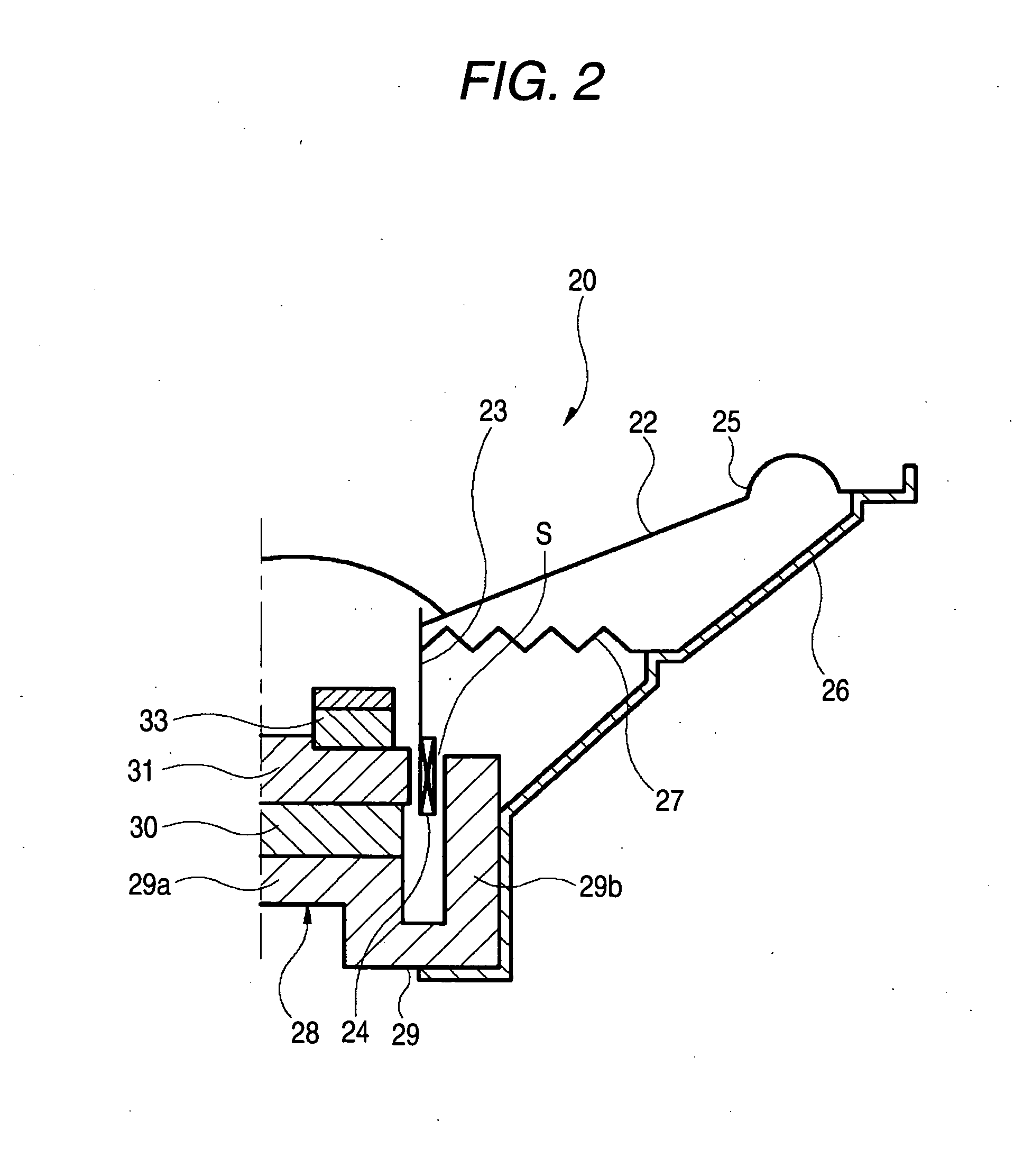
Further, when the outer diameter of the repulsive magnet 33 is reduced, a magnetic intensity in the side of the magnetic gap s by the repulsive magnet 33 is reduced and therefore, an inherent function of the repulsive magnet 33 of reducing the leakage magnetic flux to the side of the vibrating plate cannot sufficiently be achieved, as a result, there poses a problem that an initial object of increasing the efficiency of the magnetic circuit cannot be achieved.
There is a problem that when a reduction in the magnetic distortion is achieved by mounting the short-circuit ring, the outer diameter of the repulsive magnet mounted on the pole piece needs to be reduced, and an increase in the efficiency of the magnetic circuit by mounting the repulsive magnet cannot sufficiently be achieved.

Method used


Image

  • Speaker apparatus
  • Speaker apparatus
  • Speaker apparatus

Examples


first embodiment

[0027] An explanation will be given of a speaker apparatus according to a first embodiment of the invention in reference to the drawings as follows.

[0028] A speaker apparatus 40 adopts a vibrating plate 42 of a dome type. A voice coil 44 is wound around an outer periphery of a voice coil bobbin 43 connected to an outer peripheral edge of the vibrating plate 42. The outer peripheral edge of the vibrating plate 42 is bonded with an edge 45. The outer peripheral edge of the edge 45 is fixed to a speaker frame 48 by being pinched by a ring holder 46 and an edge holder 47.

[0029] The speaker frame 48 is configured by a bottom wall portion 48a disposed on a back side of the vibrating plate 42, a peripheral wall portion 48b substantially in a cylindrical shape formed by being extended from an outer periphery of the bottom wall portion 48a to a front side (side of vibrating plate 42), and a flange portion 48c expanded to an outer side in a diameter direction from a front end of the periphe...

second embodiment

[0047] As shown by FIG. 7, a speaker apparatus 60 of a second embodiment which differs from the speaker apparatus 40 of the first embodiment in a following configuration. The inner periphery of the front end side of the cylinder portion 52b of the yoke 52 is formed with a step portion (hereinafter, referred to as “a stepped difference”) 52d for butting an end face of the short-circuit ring 58 fitted to the cylinder portion 52b. By butting the end face of the short-circuit ring 58 to the stepped difference 52d, the short-circuit ring 58 is positioned in the axial direction.

[0048] Any part of the short-circuit ring 58 other than the stepped difference 52d may be common to the first embodiment. In the second embodiment the common constitution is attached with the same numeral and an explanation thereof will be omitted.

[0049] According to the structure of positioning the short-circuit ring 58 in the second embodiment, the short-circuit ring 58 can be configured by a simple cylindrical...


PUM


Abstract

A speaker apparatus comprises an inner magnet type magnetic circuit for driving a voice coil connected to a vibrating plate. The magnetic circuit comprises; a yoke; a magnet at least partly mounted at an inside of the yoke; a pole piece being attached to the other magnetized face of the magnet at the inside of the yoke; a repulsive magnet both faces being magnetized to polarities reverse to a polarity of the magnet and attached on a surface thereof of a vibrating plate side of the pole piece; and a short-circuit ring mounted and fitted to an inner peripheral portion of a front end of the cylinder portion of the yoke.

Description

CROSS-REFERENCE TO RELATED APPLICATIONS [0001] This application is based on and claims the benefit of priority from the prior Japanese Patent Application No. 2005-336355, on Nov. 21, 2005; the entire contents of which are incorporated herein by reference. BACKGROUND [0002] 1. Technical Field [0003] The present invention relates to a speaker apparatus, particularly relates to a speaker apparatus integrated with an inner magnet type magnetic circuit as a magnetic circuit for driving a voice coil connected to a vibrating plate. [0004] 2. Related Art [0005] In recent years, in accordance with space saving formation of acoustic apparatus or the like, also according to a speaker apparatus mounted thereto, a request for small-sized light-weighted formation has been increased. For the small-sized light-weighted formation of the speaker apparatus, small-sized formation of a magnetic circuit for driving a vibrating plate is effective. [0006] Magnetic circuits integrated to a speaker apparatus...

Claims


Application Information

Patent Timeline
Patent Type & Authority Applications(United States)
IPC IPC(8): H04R11/02
CPCH04R9/06H04R31/006H04R2499/13
Inventor HAYASAKA, SHINICHIKOBAYASHI, HIROYUKITAKAYAMA, KOJI
Owner PIONEER CORP
Why Eureka
Try Eureka