
Method and device for determining a location and orientation of a device in a vehicle

a technology for determining the location and orientation of a device in a vehicle, applied in the field of telematics, can solve the problems of inadequate resolution of the problem and suffer the performance of the devi

Inactive Publication Date: 2007-05-31
MOTOROLA INC
View PDF24 Cites 97 Cited by
  • Summary
  • Abstract
  • Description
  • Claims
  • Application Information

AI Technical Summary

Benefits of technology

The present invention is about a system and method for determining the location and orientation of a device in a vehicle. This is important because aftermarket devices are being installed in vehicles at an increasing rate, and they can be positioned in many different ways that can affect their performance. The invention provides a solution to this problem by using pre-stored vehicle profiles and scan profiles to accurately locate and orient aftermarket devices. This helps to ensure that the devices are installed in the correct location and are accessible to the vehicle's occupants. Overall, the invention improves the performance and safety of aftermarket devices in vehicles.

Problems solved by technology

As mentioned above, the installation of aftermarket communication devices by end-users has led to a number of issues.
Accordingly, such solutions fail to adequately address the issue associated with the inability of aftermarket devices to accurately locate their position in a vehicle.
Without information indicating where the device is located and / or oriented relative to an occupant of the vehicle, the performance of the device suffers.

Method used


Image

  • Method and device for determining a location and orientation of a device in a vehicle
  • Method and device for determining a location and orientation of a device in a vehicle
  • Method and device for determining a location and orientation of a device in a vehicle

Examples


Embodiment Construction

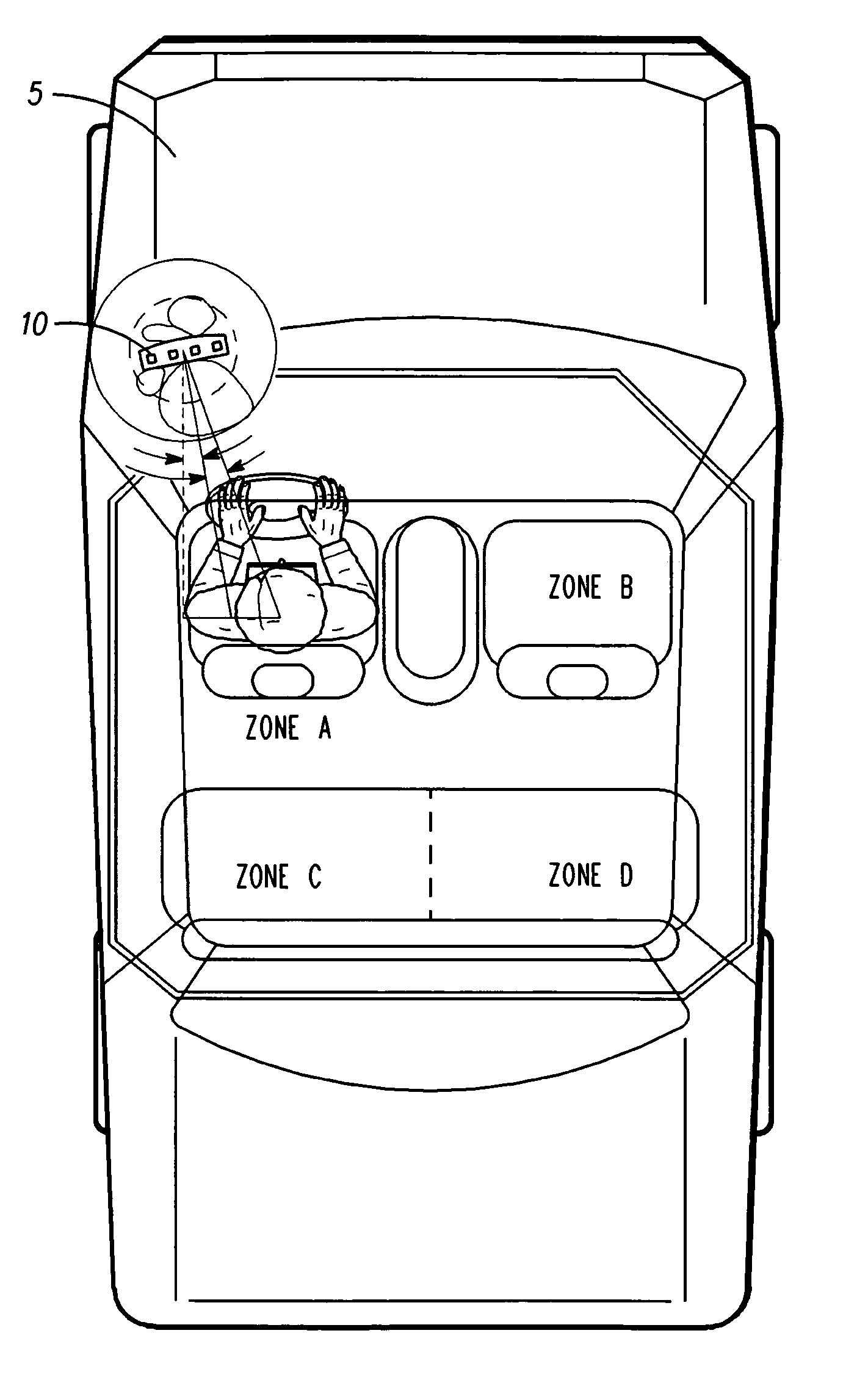
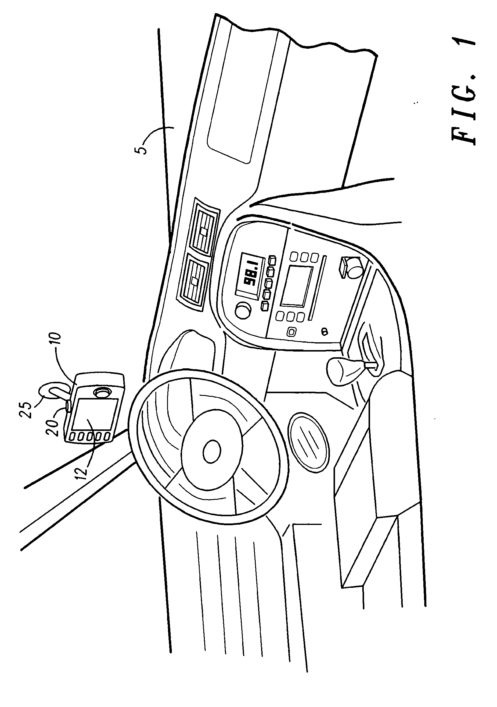
[0019] The present invention provides for systems, methods, and devices that improve upon prior attempts to solve such problems by providing a more accurate way for a device to determine its location and / or orientation in a vehicle. The device can be a factory installed device, a later installed device (e.g., aftermarket device) or a portable device. For simplicity, the examples below describe installation of an aftermarket device. The device is configured to determine its location within a vehicle by using data obtained from a rotatable location determination unit. In accordance with certain embodiments of the present invention, the location determination unit comprises a rotatable camera configured to capture images of the vehicle cabin from the vantage point of the device, which are compared to one or more stored vehicle images. These stored images are preloaded on the device by the manufacturer or distributor and can be specific to a particular make, model and year of a vehicle,...


PUM


Abstract

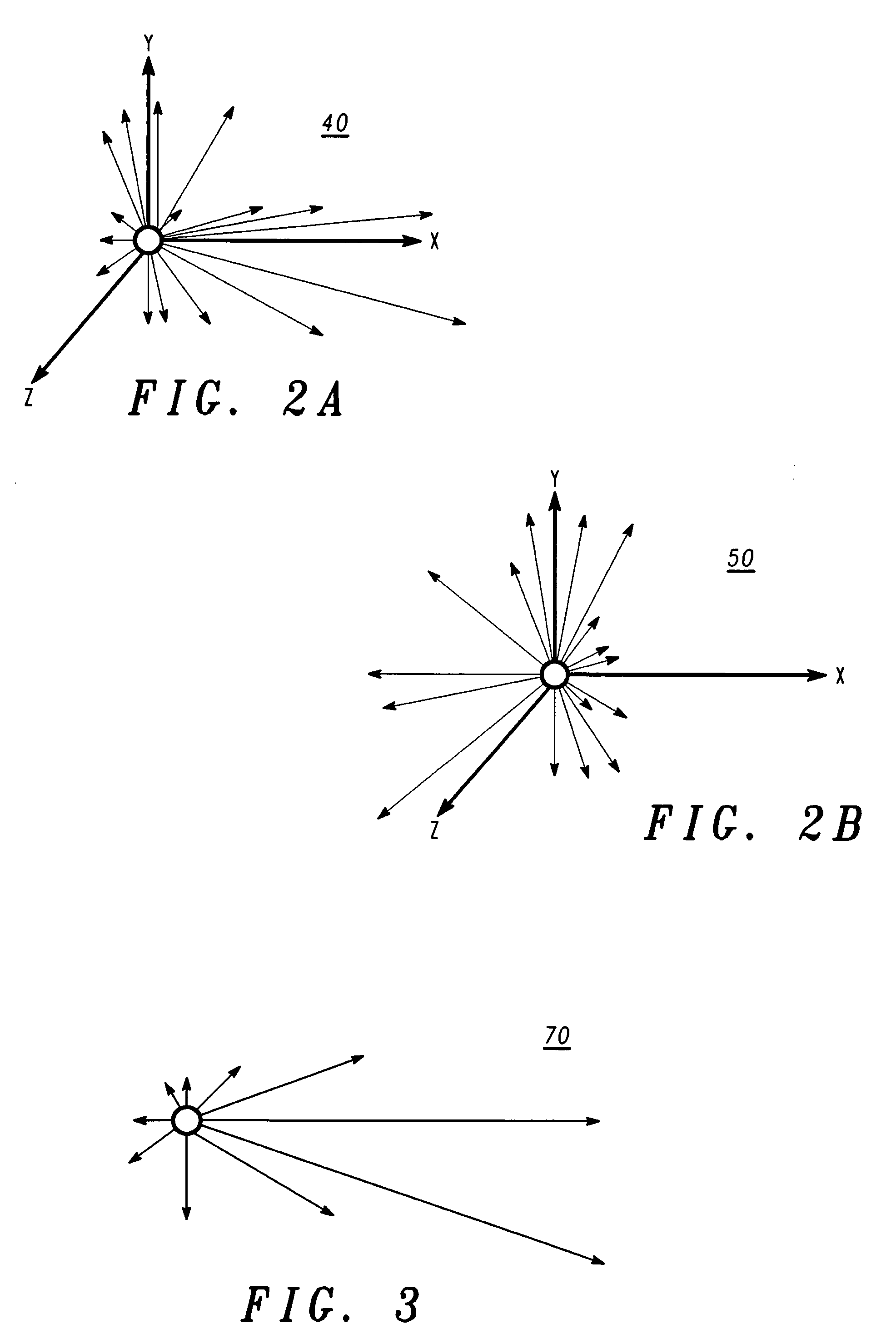
Systems, methods, and devices for accurately determining the location and orientation of adevice in a vehicle are disclosed. The ability of a device to automatically determine its location in a vehicle by using images from a camera or distance measurements is provided. The images or distance measurements are compared to previously stored data, and an image recognition algorithm or pattern recognition algorithm is used to determine the closest match and the location of the device. The camera is also configured to rotate itself such that the camera lens is substantially aligned with the user interface of the device. Upon orienting itself in this manner, the camera is configured to capture an image which allows the device to determine which occupants of the vehicle are able to access the device. In other embodiments, the orientation of the device can be determined by determining the offset angle between a reference line and the user interface of the device. The occupants having access to the device can be determined with reference to a look-up table of angles and vehicle areas. The operation of the device can advantageously be modified based upon its location and which occupants are able to access the device.

Description

CROSS-REFERENCE TO RELATED APPLICATIONS [0001] This application is related to the following commonly-owned applications, the contents of which are hereby incorporated by reference: U.S. Application No. ______ entitled “System and Method for Controlling the Processing of Content Based on Zones in Vehicles,” filed concurrently under Attorney Docket No. CM08859TC; U.S. Application No.______ entitled “System and Method for Providing Content to Vehicles in Exchange for Vehicle Information,” filed concurrently under Attorney Docket No. CM08860TC; U.S. Application No. ______ entitled “System and Method for Controlling the Processing of Content Based on Vehicle Conditions,” filed concurrently under Attorney Docket No. CM08861TC; and U.S. Application No.______ entitled “System and Method for Modifying the Processing of Content Based on Vehicle Conditions,” filed concurrently under Attorney Docket No. CM08857TC.FIELD OF THE INVENTION [0002] The present invention is generally related to the fi...

Claims


Application Information

Patent Timeline
Patent Type & Authority Applications(United States)
IPC IPC(8): G08B21/00H04N9/47H04N7/18
CPCB60K35/00B60K37/06B60K2350/1024B60K2350/1028B60R11/0235B60R11/0258B60R2011/0056H04N7/188B60K35/10B60K2360/143B60K2360/1438
Inventor AYOUB, RAMY P.SIBILSKY, BRIAN J.
Owner MOTOROLA INC
Learn More