Support system for auxiliary power unit
a technology for supporting systems and power units, applied in the field of supporting systems, can solve the problems of complex and costly manufacturing and assembly process, costly repair,
- Summary
- Abstract
- Description
- Claims
- Application Information
AI Technical Summary
Benefits of technology
Problems solved by technology
Method used
Image

Examples
Embodiment Construction
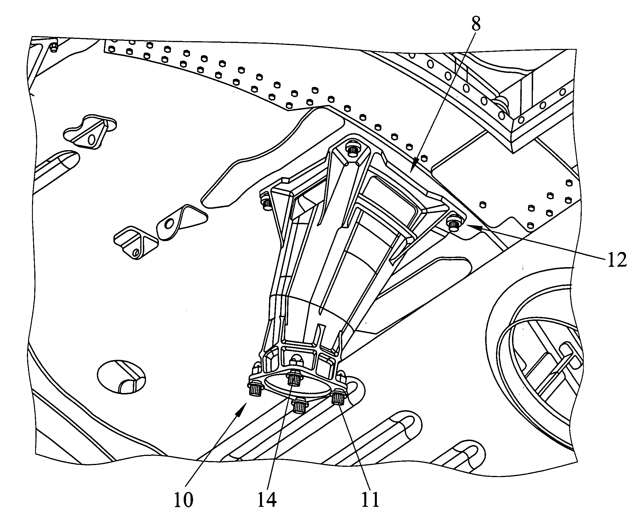
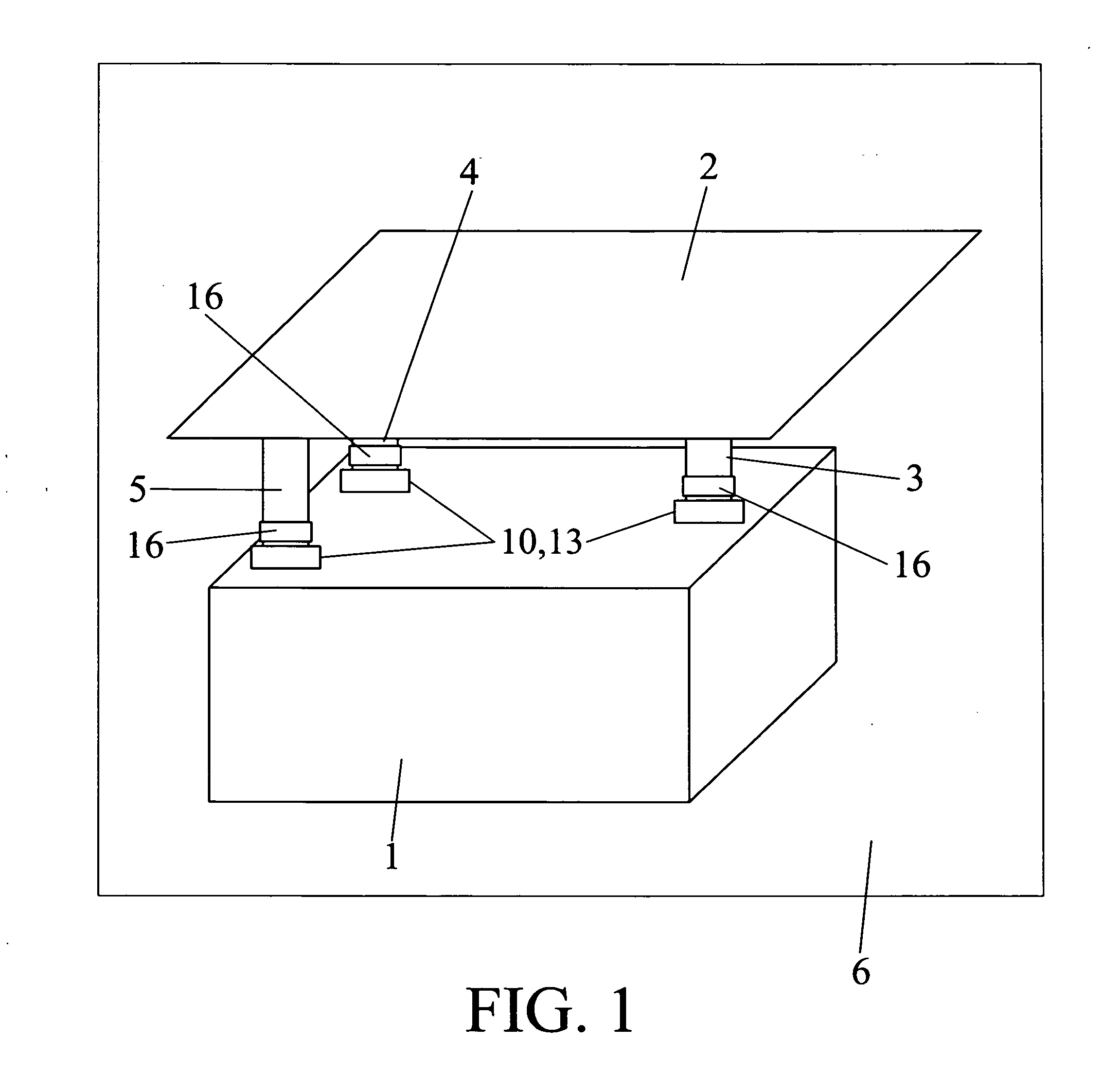
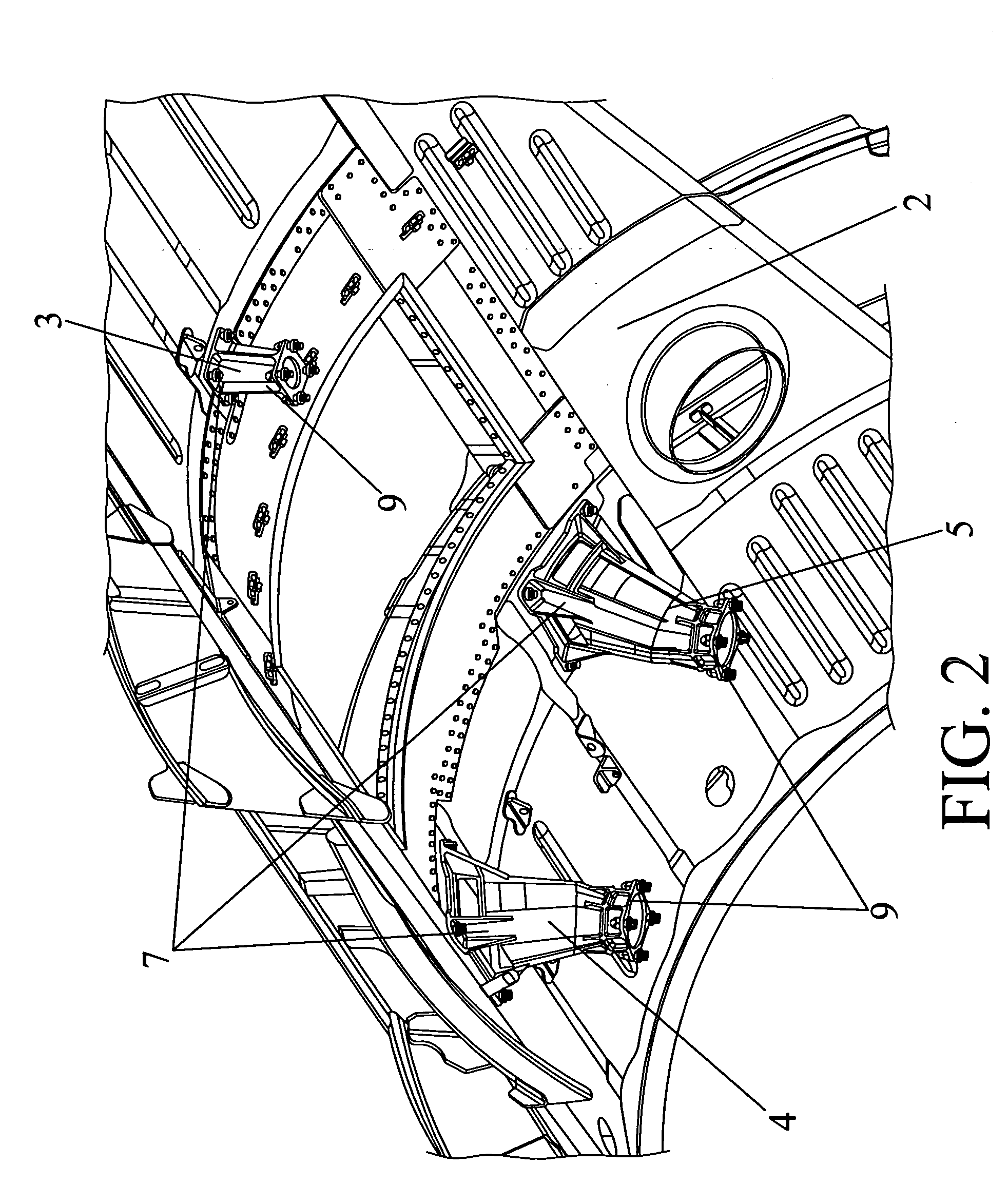
[0008] The present invention has the aim of overcoming the drawbacks of the state of the art pointed out above by means of an support system for auxiliary power unit for an aircraft. The objective of this invention is the perfect securing of the auxiliary power unit of an aircraft in the interior of the chamber where said auxiliary power unit is housed, along with improving the behaviour towards fatigue of currently existing structures, and facilitating their maintenance.
[0009] Said support system for auxiliary power unit comprises a set of at least three fittings made of an ignition resistant material, in order to prevent those fittings from being able to catch fire so that they can support the loads required in the event of fire, and also for being able to withstand the high temperatures that can be reached in the vicinity of the auxiliary power unit, without losing any of their properties.
[0010] The fittings present a shape that is substantially cylindrical. The main advantages...
PUM
 Abstract
Description
Claims
Application Information
 - R&D
- Intellectual Property
- Life Sciences
- Materials
- Tech Scout
- Unparalleled Data Quality
- Higher Quality Content
- 60% Fewer Hallucinations
Browse by: Latest US Patents, China's latest patents, Technical Efficacy Thesaurus, Application Domain, Technology Topic, Popular Technical Reports.
© 2025 PatSnap. All rights reserved.Legal|Privacy policy|Modern Slavery Act Transparency Statement|Sitemap|About US| Contact US: help@patsnap.com